| Drawing 10 - Reversing Gear, Oil Pumps, Saddle
|
| 1. Smokebox Saddle |
|
|
 |
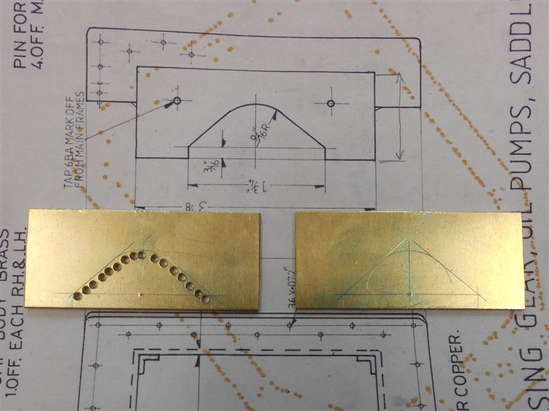
The drawing suggests using 2mm copper or brass sheet to
fabricate the smokebox saddle but I had considered making it from mild steel.
However, I couldn't find a local supplier so bought a piece of 14swg brass
sheet at the Midlands MEX and used that. First, I cut out the blanks I needed,
remembering to cut the width of the main saddle piece to the development
length to accomodate the bending of the material. The four sides of the
saddle support will be riveted together before soldering the saddle in place.
The crossways pieces are cut to fit exactly in the frames and the lengthways
pieces are cut to the nominal dimension minus two thicknesses (0.160") and
will fit between the two crossways pieces. |
 |
 |
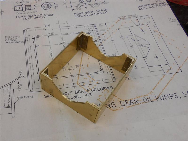
Next I marked out the cutaways and then stitch-drilled
them, removed the waste and cleaned up the shape will rotary burrs and sanding
disks. I also drilled and countersunk two rivet holes at each end for fixing
the corner angle pieces to and am using 3/64" countersunk brass rivets for
this. Once drilled, I clamped an angle piece flush with the end and drilled
through the existing hole, countersunk the opposite side and fixed the rivet,
repeating for each hole until both sides were complete. Finally, I clamped
the end pieces to the sides, drilled through and riveted these to produce
the box shape of the saddle support. |
 |
 |
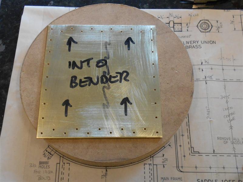
To make the main saddle piece I calculated the spacing
between holes, as this is not given on the drawing, and marked them all
out before drilling for 10BA clearance. I chose not to remove the centre
section before bending because I would have ended up with a rather weird
shape. I also turned up a piece of MDF to the size of the smokebox to act
as a former since I don't yet have the smokebox material. I don't own bending
rolls but we have some up the club so Saturday morning I took the plate
and former along for the next operation. I have never used bending rolls
so a collegue kindly gave me five minutes tuition and then left me to get
on with it. |
 |
 |
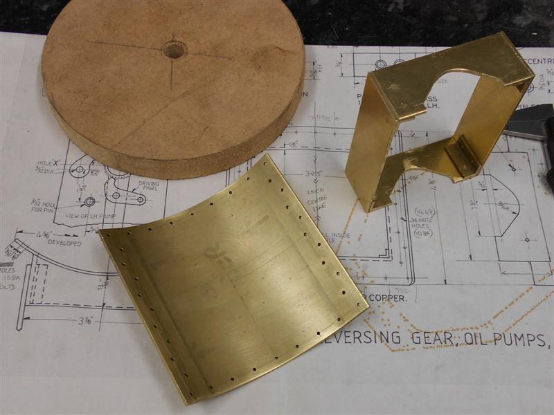
About ten minutes work saw the job complete and I have
deliberately rolled the shape a little tight as it will be no trouble to
ease it back to the exact diameter of the smokebox material but not so easy
to go back and roll it through again. I'm also aware that it is normal to
allow extra material at each end because of the leading and trailing flat
spots but I've managed to get quite a good shape without this. After easing
the circumference back to fit the template, I marked out the ends of the
saddle support and then removed the waste to leave it ready for silver soldering
to the main saddle piece. Here it is waitng to be clamped to the saddle
prior to joining. |
 |
 |
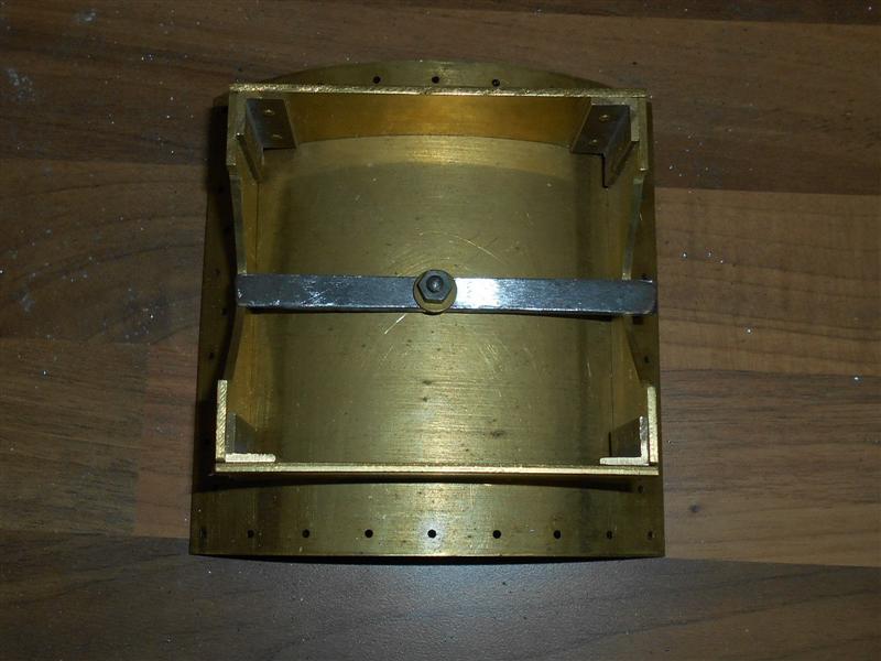
The components of the smokebox saddle needed to be soldered
together and I had to decide how to keep the two parts together during the
soldering process. I decided that the best way was to drill a hole though
the saddle and fix a cross member across the saddle support with a nut and
bolt. The main advantage was that it kept the mass down and I wasn't wasting
all my gas heating up clamps. At this point, I undid the clamp and gave
the brasswork a really good clean-up.Then I mixed up the flux and put some
on the edges of the saddle support before locating the two parts together
and clamping down again. Following this, I fluxed the rest of the assembly,
placed my pieces of solder into the inner corners and then painted the rest
of the flux over the solder. Then I assembled my hearth from my fly-ash
blocks and placed the assembly inside. |
 |
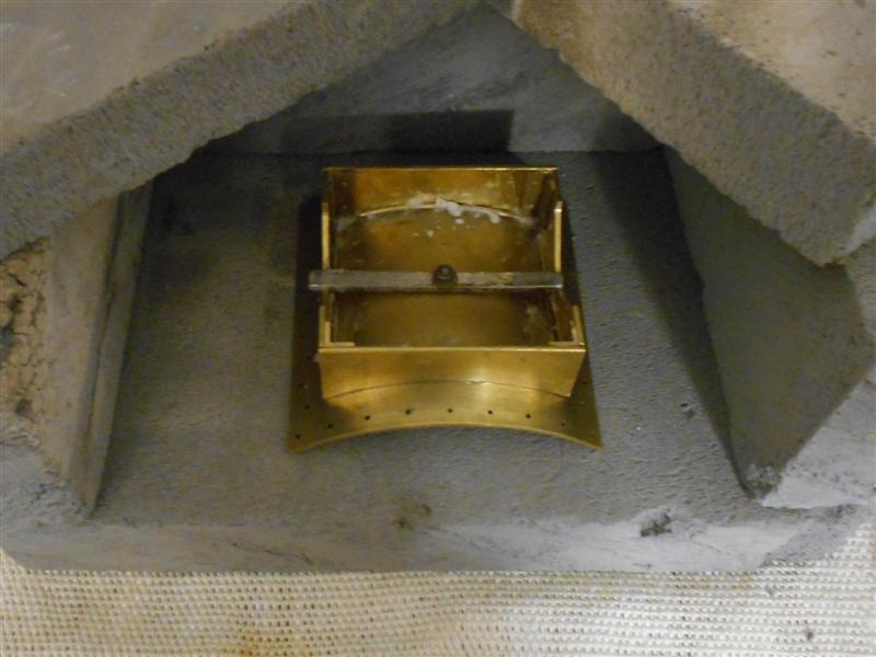
| I was approaching this job with much trepidation
but took a deep breath and off I went, directing the flame around the sides
and underneath the assembly. After a few minutes the flux had turned to
a pinkish slag, bubbling away, but the solder wasn't melting and I started
to give the occasional blast of heat over the top. The mild steel clamp
turned cherry red but the solder still hadn't melted. At this point, I chickened
out and turned off the heat. I decided to mix another load of flux, a little
more watery this time, and applied this liberally around the area. A moments
thought made me realise that if the solder hadn't melted, then I couldn't
have got it hot enough. So this time, I took no prisoners and really blasted
the flame into the area and wached the whole assembly start to glow. And
then, as if by magic, the solder started to melt at the front and slowly
crept along the sides and across the back until it was all gone! I kept
the flame going for another five seconds or so until I was sure the solder
had all melted, then turned off the gas. This photo was taken twenty seconds
after removing the heat. |
 |
 |
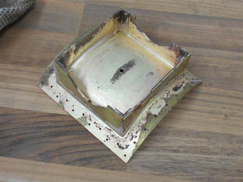
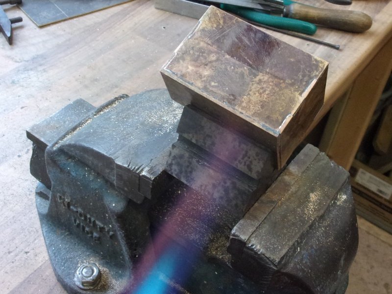
Once it had all cooled down I gave the assembly a good
scrub in clean water but had to use an old sciber to get rid of the remaining
encrusted flux and had a good hard look to ensure that a decent joint had
been made. I'm pleased to say that the solder has flowed evenly throughout
and appears to be quite a good joint. It now needs a really good rub-down
to improve the appearance, and I have spent ten minutes or more with emery
cloth trying to clean it up but I will give it a few minutes in the shot-blast
cabinet later to see if that will speed up matters. It did, and here is
the final result. |
 |
 |
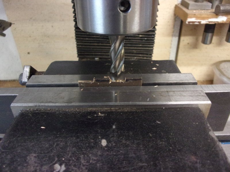
And to finish the job off, I loaded the assembly to my
large vice on the mill and removed the central area where the pipes come
through. I just need to spot through the frames to mark the boltholes and
this part is finished. |
 |
| 2. Lubricators |
|
|
 |
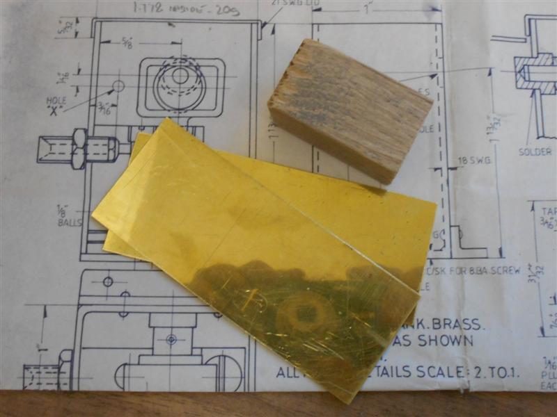
There are commercial lubricators available but I thought
I would like to have a go at making my own and decided to make the tanks
first. I didn't have 18swg brass in stock so chose to use 20swg instead.
I started by making a hardwood former to bend the material around, making
the former a little larger to suit the thinner material and preserve the
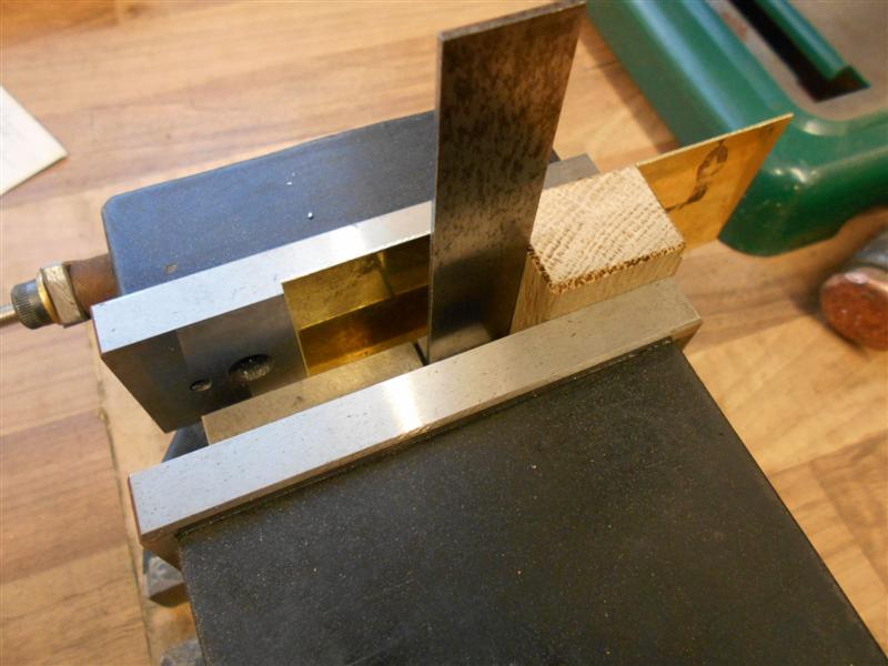
outside dimensions. A pair of brass strips were cut 1.7/8" wide by 5" long.
I made use of my large milling vice to get the first bend square, positioning
the former level with the end of the jaws. |
 |
 |
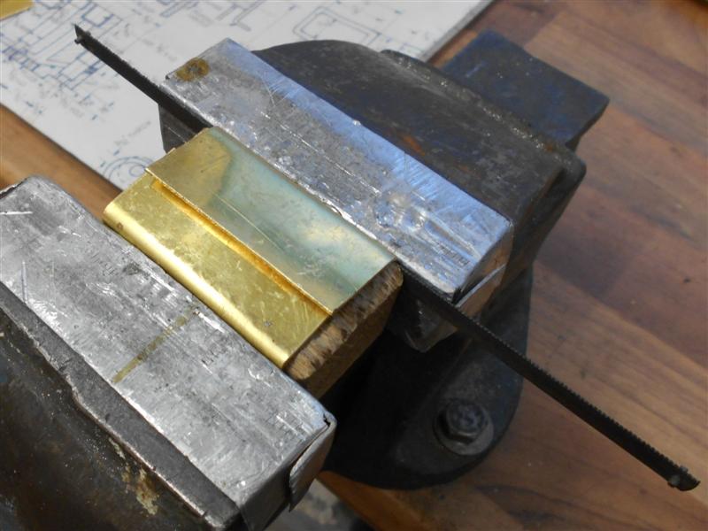
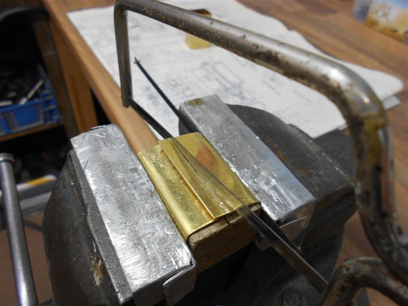
With the first bend accurate, I was able to finish the
other sides using the bench vice, finishing with the final side overlaying
the first side. Before removing the waste, I removed the former, inserted
a junior hacksaw blade in the fabrication and re-inserted the former before
clamping up. The waste from the two overlapping sides was then removed using
a junior hacksaw, the packing blade ensuring that when the gap was closed
the tank would become square. |
 |
 |
The larger of the two offcuts was then cleaned up and
used as a soldering strap at the back of the tank. A recess was milled into
the hardwood former to clear the strap and pushed back into each tank section
in turn to enable milling the ends square and to finished length. |
 |
 |
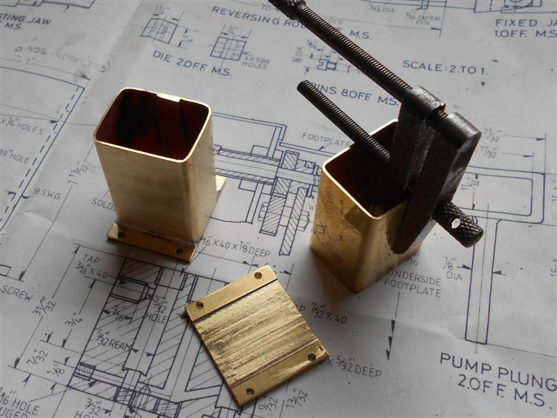
A pair of base plates were cut from 14swg brass sheet,
squared up and the centre section milled away by about twenty thou to create
a location for the tank sections, followed by drilling the mounting holes.
Then the bases and tank sections were soldered together, the clamp in the
picture being used to ensure the earlier solder didn't fall apart. The bases
had taken on a slight bend after soldering and each was reloaded to the
mill and skimmed flat. It was only a few thou but enough to cause rocking
of the assembly. To finish, the various holes were added to the tank sides
ready for the pump components to be fitted. |
 |
 |
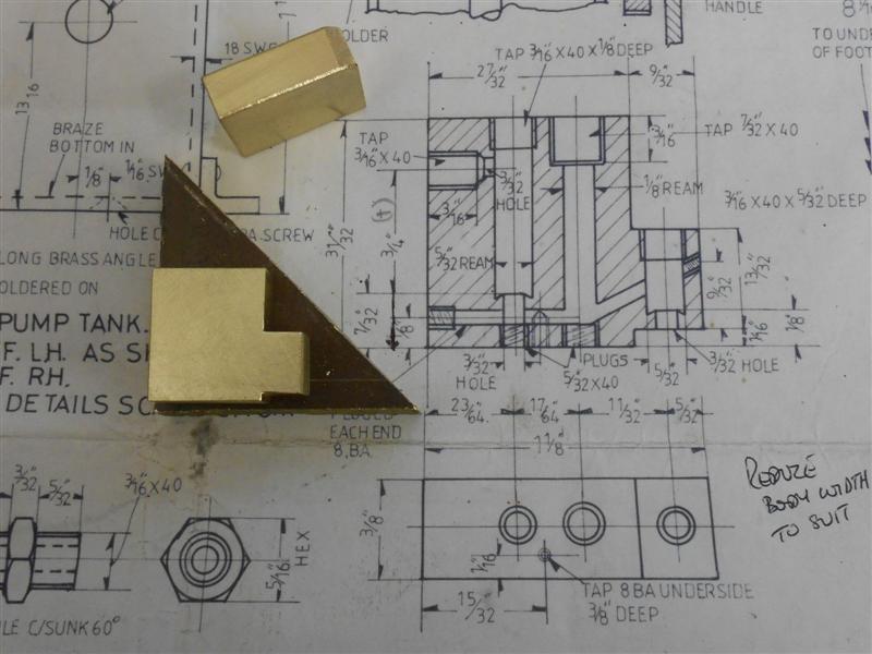
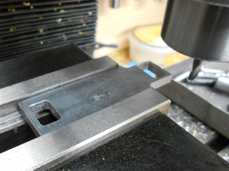
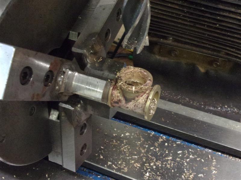
The body of the lubricator pump should be brass but I
have used a couple of offcuts from some bronze plate that I worked on recently.
The bodies are 3/8" thick so I was able to machine all round to get them
to size. I have added a clearance chamfer at the bottom because of the solder
in the tanks. All the drilling, tapping and reaming operations were done
on the big mill using co-ordinate positioning because all holes are on the
same centre-line so I only had to set the "Y" axis and leave it locked all
the time. |
 |
 |
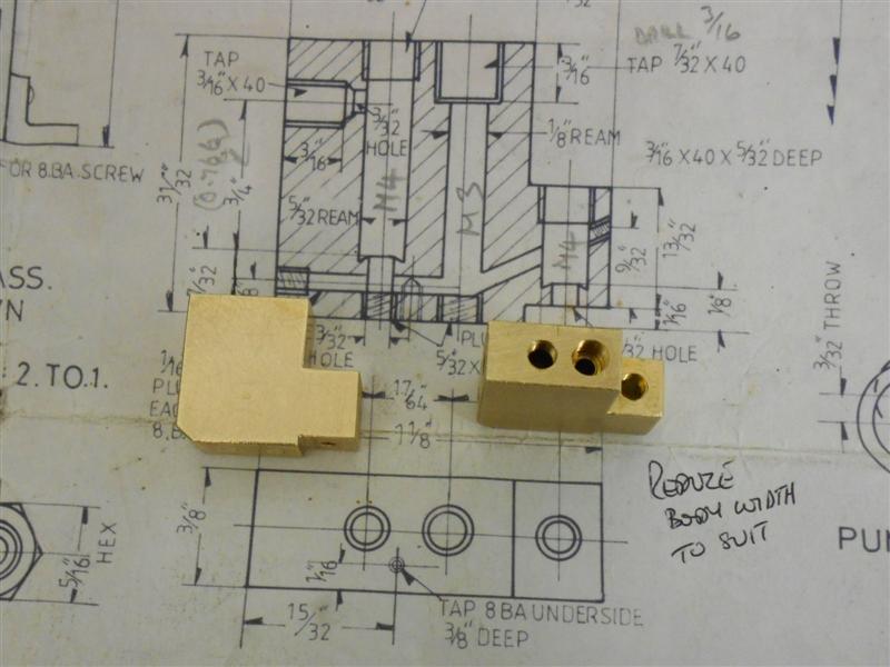
To suit my tooling, the 1/8" reamed hole has been made
as 3mm and the 5/32" holes as 4mm. Threads are all 40ME or 8BA, as specified,
except for one blanking plug that I drilled the wrong size hole so went
to 6BA instead. The one awkward hole was the inlet channel which is at twenty-five
degrees to the horizontal. For this, I used a slot drill to create a small
island to start the drill, and had a piece of sacrificial material in the
cross-hole so that the drill didn't wander as it crossed over. |
 |
 |
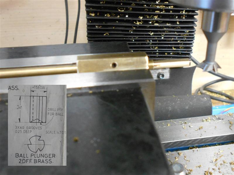
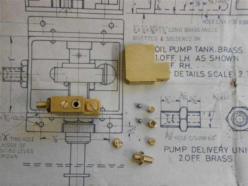
The collection of plugs, unions and other assorted pieces
were all made from brass bar. The only part that was not straightforward
was the shuttle on the outlet side which required some grooves milled in
the sides to allow the oil to flow. After turning to size on the lathe,
the three grooves were put in using a dovetail cutter on the mill. A piece
of hexagon bar was used to index the three sides as it was quicker than
setting up the rotary table. Apart from the piston and the spring, these
are all the parts that make up the body of the pump. |
 |
 |
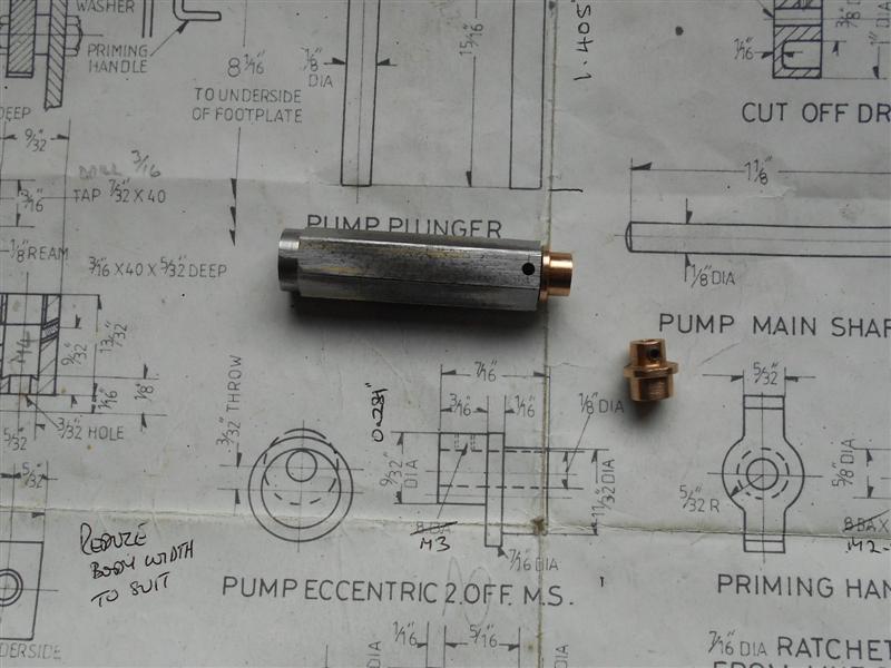
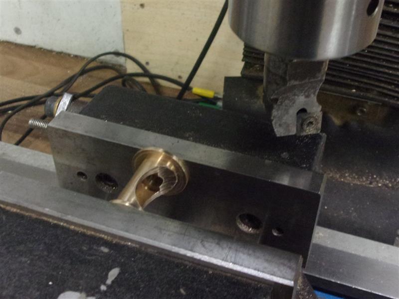
Next up was the plunger. To make the plunger and collar
I started with some 5mm flat black bar intending to make the whole thing
in one go. Two are required and I cut material to make both by splitting
after milling. A pair of pilot holes were drilled first followed by milling
away the internal form with a 1/8" slot drill. The dimensions on my sketch
are the plus and minus co-ordinated from the hole centre for machining to
finish size. Moving to a larger cutter for more rigidity, the outside form
was produced next leaving a 1/16" thick wall all round.. |
 |
 |
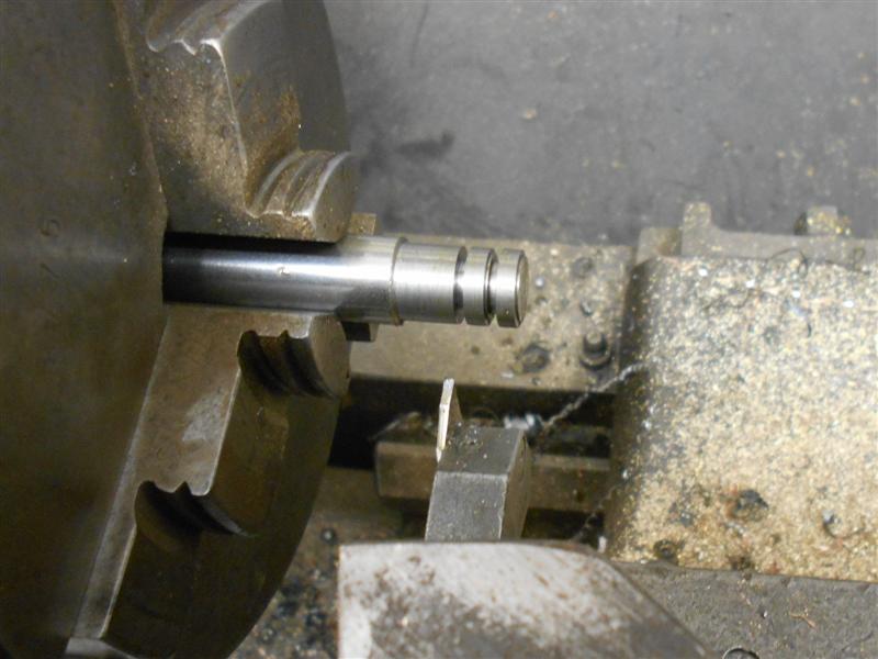
Finally, the workpiece was held vertically in the vice
and the waste cleared away to leave the shape shown. This was then sawn
in two and then it was over to the lathe to turn the 3mm diameter using
the 4-jaw chuck and a small supporting centre. However, after wrecking one
of the pieces because of a poor setup, I decided to take a different approach.
The leg was sawn off, a small boss milled and an M3 hole drilled and tapped
into the end. Into this was screwed a length of 3mm stainless rod of the
appropriate length. Even this was too restrictive and the boss was cleared
away just prior to assembly. |
 |
 |
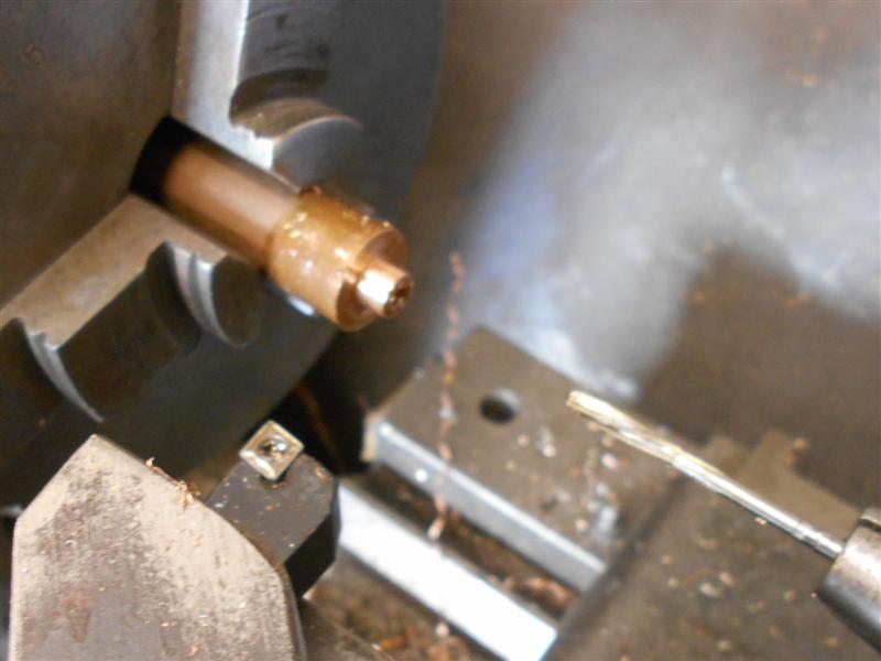
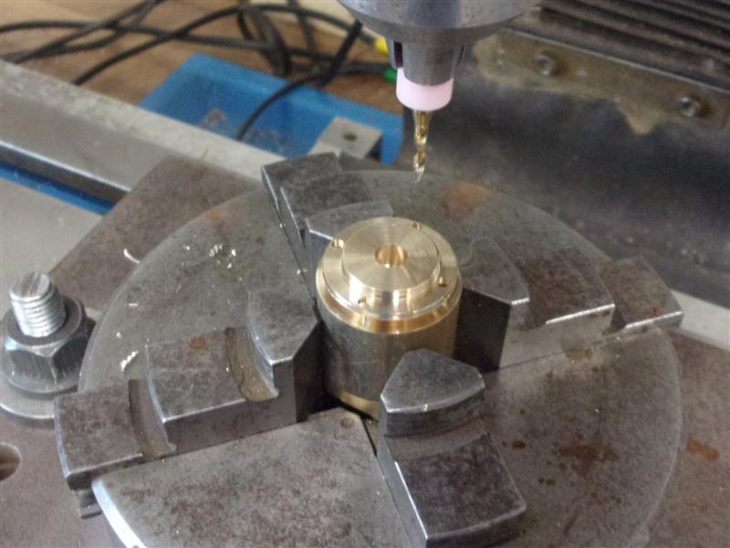
I made the eccentric from phosphor bronze although the
drawing calls for mild steel. I think it will wear better but may be wrong,
easy to replace if neccessary. There are different ways to produce eccentrics
including independent four-jaw chucks but I chose to use an offset bush
because it is repeatable without clocking up the workpiece. First I turned
the main boss, holding the 9/32" dimension to within a thou for a good fit
in the bush. I also drilled and reamed the hole 3mm, which I'm using instead
of 1/8" dia. The parent material is 5/8" diameter because the workpiece
will clean up with about ten thou to spare. Next I made the offset bush
from a piece of 3/4" diameter mild steel, turning the O/D to 11/16" dia
and leaving a shoulder for butting up against the chuck jaw, then reversing
and facing to length. The offset hole was made on the mill by holding in
a table-mounted chuck, clocking true then offsetting by the given throw
dimension of 3/32". The bush was drilled and reamed 9/32". I also made a
small brass plug to fit in the other end of the bush to ensure it didn't
distort when clamped up in the lathe chuck. |
 |
 |
The eccentrics were then loaded to the chuck and pulled
up really tight, and I mean REALLY tight, otherwise the intermittent cut
could have moved the workpiece round in the bush and ruin it. All turning
here was finished in the one visit, using the compound slide to control
lengths. To drill the locking screw hole, I made a simple drill jig from
some hex mild steel as I find this easier than trying to set up fiddly components
in vee-blocks and vices etc. I've used M3 rather than 8BA because I have
a load of M3 grub screws in stock. |
 |
 |
The drive shaft was made using 3mm stainless
steel rather than 1/8" dia material solely because it was in stock. The
various bushes are as per drawing, except for the hole size, of course,
but the rear supporting bush has been made to solder in from the outside,
rather than the inside, because of the strap at the rear of the tank. The
other variation I made was the turned and threaded part of the shaft. My
8BA button die is in very poor condition and not up to producing a decent
thread on stainless but I have M2.5 available in both HSS split die and
spiral-point HSS tap, my favourite combination of threading tools. As a
long-time machinist in industry, I really don't like carbon-steel dies or
hand taps and avoid them where possible. The part called "adjusting bush"
with its locknut is straightforward turning and threading with tap or die,
as appropriate, but I'm not sure what it's meant to adjust - it bolts to
the tank and is simply a support. The priming handle has been made from
3/4" dia brass bar. The stem was turned, drilled and tapped first and the
handle created on the mill. A filing button was used to guide the shaping
near the stem. The picture shows the components loosely assembled in the
tank. |
 |
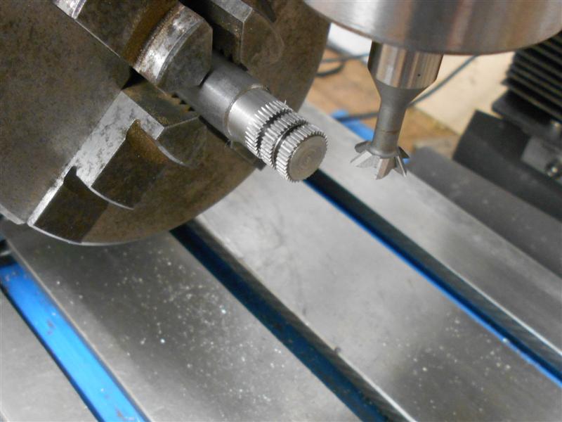
To make the ratchet, I started by skimming down to 7/16"
dia a short length of 1/2" dia bar which I aquired from a local factory
and is tough as old boots. It's BS S154 which is equivalent to EN25. I also
parted through part-way so that I didn't have an intermittent cut after
the teeth were formed. The bar was then transferred to the mill and the
teeth cut with a dovetail cutter. I have chosen to make 36 teeth because
that is ten degrees, and two turns of the handle on my rotary table and
anyway, I don't have a dividing head, I went round three times before I
was happy with the depth and then returned the bar to the lathe drilled
the hole and finished parting them off. |
 |
 |
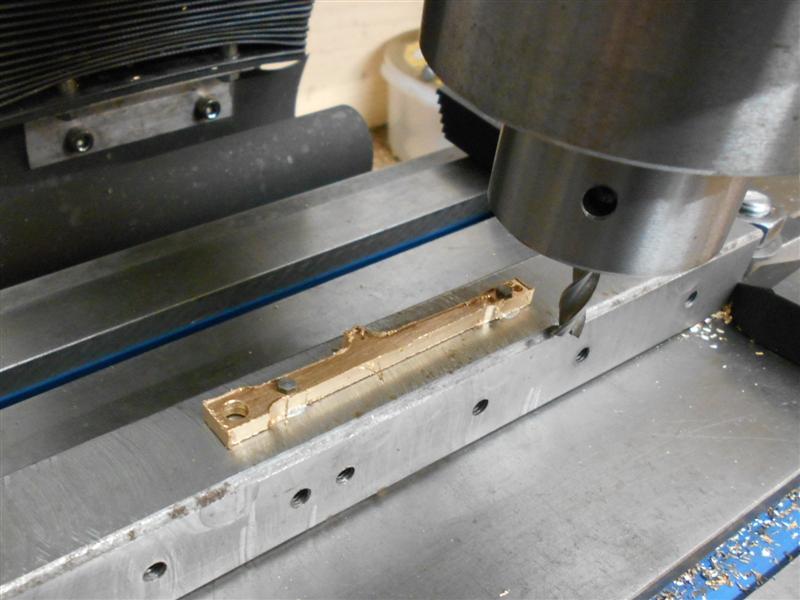
I've chosen to make the lubricator operating levers from
16swg brass because I have a box full of brass offcuts to use up. They would
just about come out from 1/2" wide strip but the holes would need to be
offset quite accurately to make it work so I used some 5/8" approx pieces.
Although they are left- and right-hand, they are symetrical so I made them
as a stacked pair, starting with the holes. These were co-ordinate drilled
using the DRO on the mill. |
 |
 |
I then set up one of my universal milling fixtures and
drilled a matching pair of holes for clamping the work down with. The two
levers were bolted down using 8BA bolts and with small washers underneath
for some cutter clearance. It only needed a few thou. I then roughed out
the maximum dimensions at the head, tail and spring-mount positions. Once
I had those dimensions correct, I then needed to skew the jig over to form
the tapered shape. I don't have any slip gauges but an appropriate sized
drill was good enough to provide the correct offset. |
 |
 |
I didn't want to unbolt the work from the fixture so
had to move the jig in the other direction also, just using a combination
of smaller parallel and drill to get the same amount of movement on the
other side. Here is the final side just finished. The rest was just filing
and linishing, a filing button being used at the head end and freehand at
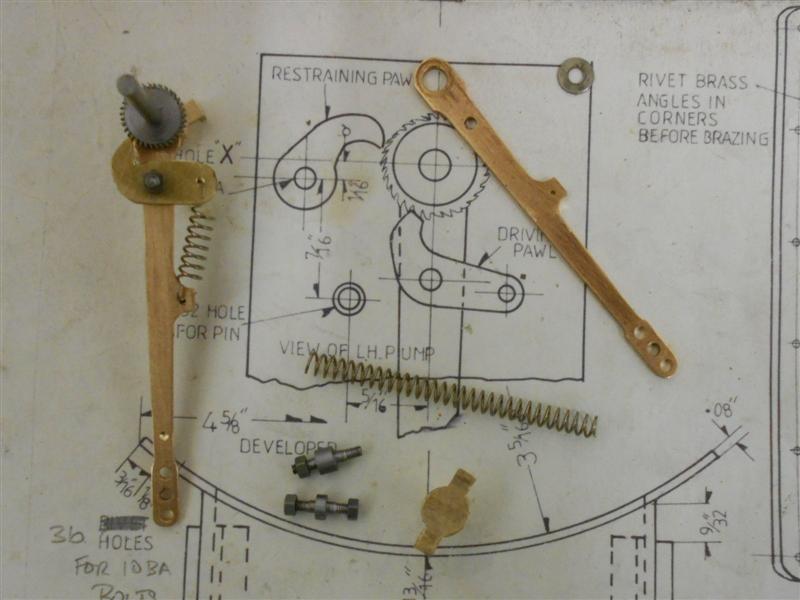
the bottom. Four pivots were needed and these were made next on the lathe
using 3/16" dia mild steel, simple turning and threading, and then it was
onto the pawls. I have made these from 1/16" brass as a temporary item to
check "proof of principle" and to create a pattern. They will be remade
when I get some ground flat stock. |
 |
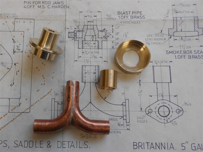
| 3. Blast Pipe |
|
|
 |
I started the blastpipe by getting a pair of 15mm slow
bends from the plumbers merchant and cut away the two outsides, as shown
to the left. I then set up the chuck on the mill table in an attempt to
machine the edges down to the halfway point. The Hoffman roller is being
used as packing but the setup was nowhere near rigid enough. |
 |
 |
Instead, I set the parts up in a vee-block and used a
1/2" diameter bar to hold them in place. A more complicated setup but
one that held the work well during machining. A 3/16" end mill is being
used, taking ten thou per pass to lessen the chance of something going wrong. |
 |
 |
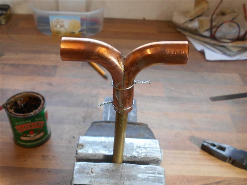
The two parts were then fluxed, brought together and wired
and finally soldered using silver-bearing soft solder. The two flanges were
turned from 1.1/2" diameter brass bar. Moving to the mill, the flats
were first milled away followed by drilling the 4BA clearance holes for
fixing to the frames |
 |
 |
To create the lozenge shape, they were loaded on two pins,
as shown to the left, and the final shaping done freehand. The assembly
has to fit between the frames with fifteen thou of gasket material on each
side so the pipework component was milled to suit. After finding the centre
and zero-ing the DRO, cuts were taken at plus and minus until the correct
width was obtained. For me, this was about 52 thou on one side and 14 thou
on the other and leaves the vertical section dead central between the frames. |
 |
 |
The blastpipe nozzle, as drawn, cannot be made as a single
component. I have made it in two parts, starting with the lower body, turning
the O/D and screwcutting the internal 3/4" x 32tpi mounting thread.
This was then reversed in the chuck and the 3/4" diameter section turned,
leaving a 1/8" wide flange at the base. I also turned a small mounting
spigot on the flange to locate the upper part. This upper ring was made
from the same 1.1/2" diameter material and was machined to fit on the
body. |
 |
 |
The two parts of the body are ready for soldering together,
and the externally-threaded collar has been made from 3/4" brass bar
and bored to suit the soldered tee-piece. This was then squeezed onto the
pipe in the vice - the pipe is not pefectly round - using a clamp to support
the ends of the Tee, otherwise the pipework could split. The various parts
were then aligned in the frames, with a thirty-thou shim to simulate the
packing,and soldered together. The various holes were drilled in the blast
pipe collar and this was also soldered together. |
 |
| 4. Blastpipe Spacer |
|
|
 |
The blastpipe spacer was made from 1.1/2" diameter
brass, facing and turning the 1.1/16" diameter on the first operation,
and drilling an 11/16" hole before parting off a little over-length.
The billet was then reversed in the chuck, faced to length and the two bores
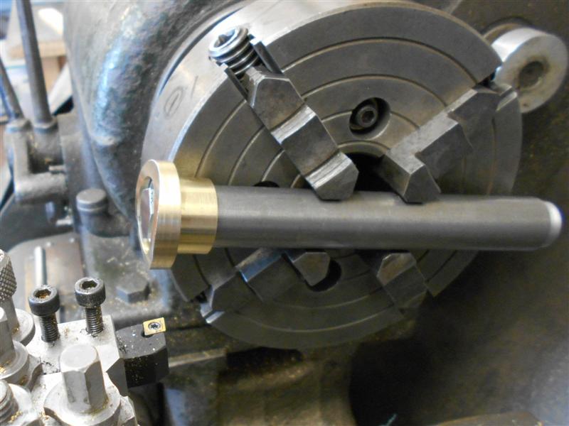
formed. To create the radius to fit the bottom of the smokebox, I made a
mandrel from a length of 7/8" diameter mild steel bar to mount the
spacer on. |
 |
 |
I turned a spigot on one end about 1/4" long and
included an M10 tapped hole and by making the bar about 6" long, there
was no need to balance the chuck. The M10 bolt was tightened with a box
spanner and faced off before mounting in the four-jaw as shown on the left.
The head was rested on the outer diameter of the chuck and a 3/32"
spacer used at the other end to square the bar to the bedway. The only thing
of note was the need to lock the cross-slide before each ten-thou pass to
stop the slide being dragged in by the cut. Shown on the right is the finished
article, which fits quite well in the base of the smokebox.. |
 |
| 5. Blast Nozzle |
|
|
|
The blastpipe nozzle, as drawn, cannot be made as a single
component. I have made it in two parts, starting with the lower body, turning
the O/D and screwcutting the internal 3/4" x 32tpi mounting thread. Because
it goes tight to the back, I kept the half-nut engaged and turned the chuck
by hand. A thread this fine only needs five or six passes. All the bores
were done at this stage also. This was then reversed in the chuck and the
3/4" diameter section turned, leaving a 1/8" wide flange at the base. I
also turned a small mounting spigot on the flange to locate the upper part.
This upper ring was made from the same 1.1/2" diameter material and was
machined to fit on the body. |
|
|
The two parts of the body are ready for soldering together but this is
the only picture I have of the two parts before joining, the blastpipe
and threaded collar have been seen before. Finally, the component was
loaded back in the lathe and the top angle produced with the compound
slide set round to about twenty degrees. The ring of thirty-thou blower
holes were done on the mill using the six-hole solution from the Zeus
book. The position of the hole for the steam entry fitting to the blower
ring will be marked once I've assembled all the components together. If
I do it now, Sod's law determines that the hole will be in the worst position
possible.
|
 |
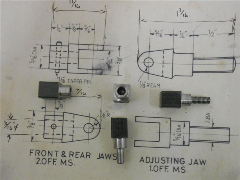
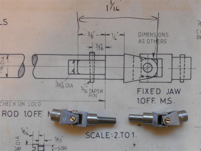
| 6. Reversing Rod & Joints |
|
|
 |
The reversing rod joints have been made from some 1/2"
square black bar which is a little oversize and can be milled to size. There
are four forks to make, two of which are the same, and a pair of pivot blocks
with the pins. After sawing the four billets from the stock, the shoulders
and other turning ops were done in the self-centering four-jaw chuck. Concentricity
is unimportant because I will mill the sides to size next so I have just
loaded the 4-jaw to the 3-jaw chuck for quickness. Note the tape round the
3-jaw chuck! After twice in the past dropping the 4-jaw onto the bedway
because I undid the wrong chuck - the keys are the same size - I do this
automatically now. Since the front ends are all the same, I was able to
load a backstop behind the chuck and drop each part in and turn all the
shoulders to the same settings. The two differing ones had the other sections
free-turned. |
 |
 |
For the next operation, I loaded the 4-jaw back onto its
mounting plate and set it up on the mill, accurately setting the centre
to X0,Y0 on the DRO. Each component was loaded in turn and a 3/16" dia slot
drill used to rough out the slot using fifty-thou depth of cut at each of
the six passes. This was then changed to a 1/4" dia slot drill and the slot
finished with a single pass at 5/6" deep. The same tool was then lowered
to just touch the packing washer and the outside was then machined all round.
This was simply a case of starting at 0.312" on one axis and winding to
the same setting on the other side, repeating all the way round. The holes
for the pivots were put in using a 1/8" dia slot drill and the shaping of
the fork was done freehand on the linisher and with files, a filing button
being made to help shape the radius on the end. |
 |
 |
The pivot block has been made from 1/4" square mild steel,
dressed down to move easily with the space of the forks. I used my small
vice with the soft jaws for drilling the holes because I can rest the work
on the jaw steps and up against the milled-in end stop. Getting these positioned
accurately is quite important or the pivots wont line up properly with the
holes in the forks. I don't have 5BA taps, nor any screws, but I have lots
of 1/8" Whit screws and a tap so this was used instead. The screws I've
used are slotted brass round-heads which were turned down to a bare 1/8"
dia on the head and then cut off with a small amount of thread for fixing
into the block. These are all the parts that make up the two UJ's but the
shaft can wait till later. For this reason I have not put in the taper pin
holes, they will be drilled at assembly time. |
 |
| 7. Lubricator Drive Rods |
|
 |
The lubricator drive rods have been made from
3/32" dia stainless steel with the ends turned down to 0.087" and threaded
8BA. The forks were made from 3/16" square mild steel, turning the front
boss and drilling through 1.8mm and parting to length. Moving to the mill,
the 3/32" dia cross-hole was drilled first. Then they were loaded to the
four-jaw SC chuck, rotated by eye to line up the cross-hole and, very carefully,
the slot put in with a 1.5mm end mill - twenty thou depth of cut and a very
slow feed.,The 8BA threads were tapped on my small tapping fixture, held
with pliers and, finally, the rods were bent front and rear to align with
the lubricator and expansion link drive arms although the photo was taken
before bending. |
| 8. Reverser Box |
|
|
 |
I've made the reverser box from offcuts of 16 swg brass
sheet and soldered them together to get the basic shape. I drew out the
parts with locating tabs included and hacksawed to size. The tabs were marked
with a felt tip to ensure the correct orientation. Cutting the tabs was
a simple matter of setting each side in the vice with packing to leave about
1/8" sticking up. Then it was touch the top with the cutter, go down 1/16",
touch the end, zero the DRO and wind to 0.375". Because I used a 3/8" cutter,
I wound along to 1.125" and came through with the centre slot. I did this
for all the pieces. |
 |
 |
Next, adjacent sides were soldered together by resting
each pair in a spare Vee block to keep them square. This is silver-bearing
soft solder and an alkaline flux. Following this, the first and second pair
were joined together to form most of the box. The solder was laid in the
bottom and heat applied from outside, as with silver solder. The clamps
and bracket kept things square but doubled as heatsinks, too. |
 |
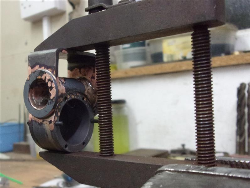
 |
Getting the inset section into place was more of a challenge
and was achieved with this Heath Robinson setup, doing both joins a few
minutes apart. I haven't yet soldered the joins and the solder can be seen
laying in the corners. The base was put on next, starting with the longest
edge. The clamp was to prevent the top bit dropping loose because it seemed
the most vunerable to collapse. By having the Vee block tipped over in the
vice, gravity was helping keep thing in the right place. |
 |
 |
I actually spent more time heating the Vee block than
the component as it gave me better control of the temperature. The moment
the solder melted, I pulled away and let the residual heat do the work.
A bit like a giant soldering iron. The overlapping section was sawn away,
the corners and edges fettled and this is the basic box ready to be drilled
and have the various bushes fitted. |
 |
 |
The mounting bracket for the reverser box is a piece of
16 swg brass bent around a simple former with the joining edges solder afterwards.
Going back to the box, the next job was to linish all the corners, particularly
around the base. Having the base soldered on made it rigid enough to hold
in the vice and mill all around the top to bring it to finished height. |
 |
 |
After this, the holes for the bushes were drilled and
reamed as well as holes in the base for fixing to the platform and for the
bearing to hold the driven shaft. The bearings for the driving shaft were
soldered in first, followed by line reaming. I'm using a pair of bevel gears
from the "useful oneday" box rather than the specified meccano gears, purely
a financial consideration. I've had to redesign the innards to suit the
gears I'm using and the support for the driven shaft had to be located behind
the gear. This is an offcut from the bronze plate, milled complete so it
acts as both bearing and support pillar. |
 |
 |
The driven shaft was offered up to set the location of
the support bush and holes drilled in the bottom of the box to suit. Then
the rest of the bushes were made and soldered in, the Meccano worm and gear
pair drilled to suit the shafts and the indicator drum made from some 1"
dia HE30 aluminium alloy. The drum will be marked out later. The UJ and
drive fork were covered half a papge up. |
 |
 |
Finally, the lid was made from another piece of 16 swg
brass, the shape formed by scribing round the outside of the box. A locating
piece was soldered to the underside at one end and a fabricated spring clip
soldered to the opposite end. For the top of the lid, a small pointer was
made from brass shim and fixed with 3/64" rivets, then bent to suit the
indicating drum. |
 |
| 9. Reverser Handle |
|
|
 |
Just for the hell of it, I decided to make my own handwheel.
I found a billet of 1.1/2" dia brass with a hole through wich looked suitable
for the job. Thoughts turned to the problem of making a large curtain ring
and soft jaws seemed the way forward. For the benefit of people unfamiliar
with soft jaw use, here I'm truing up the jaws before loading the work.
Because I will be holding in the bore, I have opened the jaws outwards onto
a setting ring. Then the jaws are skimmed for a nice fit in the bore. When
using soft jaws, it's important to always use the same key hole each time
to compensate for any wear in the scroll, hence the mark on the chuck. |
 |
 |
Using these jaws meant I had good all-round access to
the part and the first forms made were the inner and outer radii using hand-ground
HSS form tools. I'm not after a perfect circle, this can be filed or sanded
to shape. Next, I parted part-way through then followed with another form
tool to make the back radius. |
 |
 |
Then I returned to the bore and eased this out to final
diameter and also deep enough for the parting tool to break into. Then it
was cut off. Time to change the jaws over and grip on the outside. Once
again, soft jaws allow the component to sit in a machined recess making
it easy to form the last internal radius. Using soft jaws like this stops
the component deforming with the pressure from the chuck jaws. |
 |
 |
So here is the finished ring, approximately the same size
as the drawing, waiting for the spoke holes. Because there are five spokes,
it made the options for holding the work a little more limited and I opted
to make a holder from 12mm MDF. |
 |
 |
I've drilled a 10mm dia pilot hole and bored out a recess
so that the ring is a press fit into it. That is only about two thou interference,
though, it's already a fairly well-compressed material. I marked out a rough
pentagon and sawed some of the waste away before putting a 10mm bolt through
the hole, with a locking nut on the back. |
 |
 |
This was then loaded to my rotary table. A decent-sized
endmill and a mask, something I think is essential when machining MDF, and
I was ready to form the outer shape. 72 deg. steps and three rotations to
get the correct form. The spokes are at twenty degrees to the horizontal
and the tilting vice was used to hold the ring at the correct angle. Each
of the five holes was drilled 2.5mm to allow a bit of movement for the 3/32"
diameter spokes. |
 |
 |
Next I made the boss from some 1/2" dia brass and this
needed a 20 deg. angle at the front for the spokes. It wasn't worth moving
the compound slide round so a tool was set using an angle gauge. Setting
up to drill the holes was much more fun, needing two angle plates and much
moving of positions to get it to work in the available space. I need a large
angle plate without webs, something to look out for next time I go to a
show. |
 |
 |
After drilling all five holes through to the bore, the
rotary table was returned to it's normal mode and a M3 cross-hole drilled
and tapped. Then the bar was returned to the lathe and the boss parted off.
I worked out that the spokes needed to be 19/32" long and these were cut
with a junior hacksaw. However, it turned out they were a bit too long and
needed trimming down to 9/16". Getting the wheel assembled was a long, drawn-out
process but I eventually managed to get all the parts together by starting
with the spokes resting in the boss and slowly pushing a pointed 3/16" diameter
rod into the centre and slowly working the spokes into the holes on the
outer rim. |
 |
 |
The rod already had a couple of cross-holes in it and
I was able to rest the assembly on a panel pin poked through the rod. The
joints were all soldered with silver-bearing soft solder. Unfortunately,
this did end up with the rod soldered to the boss so that had to be returned
to the lathe and be drilled out. After cleaning that up, the handwheel was
returned to the holder and the hole for the handle drilled. Then it was
tapped 8BA on my small tapping fixture. |
 |
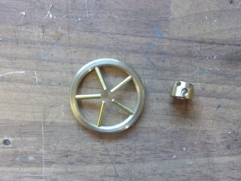
 |
The handle was made from 3/16" dia brass, the shape being
formed solely with files and abrasive cloth, and the back turned and threaded
8BA. Meanwhile, the wheel has been cleaned up in the shotblast cabinet.
And, finally, primed and assembled to the reverser box along with the mounting
bracket. |
 |
| 10. Reverser Mk 2 |
|
|
 |
The reverser box is too big for the space - another poor
piece of design and drawing - so I have decided to remake it using the existing
gears and handwheel but more in the style of the prototype. I haven't found
any good photos of the BR reverser box but Adam Cro has drawn (and sells)
a 7.1/4" version and I have used his drawing as a guide. The unit can be
broken down into two basic sections, one being a right-angle drive and the
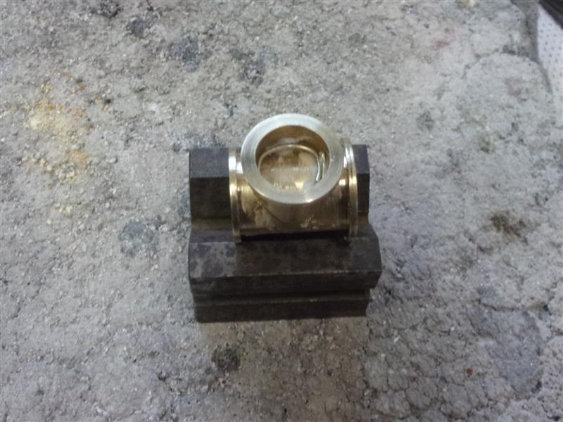
other a worm and wheel pair to indicate position. I started with the right-angle
drive box by machining up a piece of brass bar to create a tube with two
flanges and a second piece with one flange to silver-solder to the side.
After turning, I set up a chuck on an angle plate to mill the end profile.
The two parts were set on a vee-block, well fluxed and a ring of silver-solder
placed inside the branch. Heat was applied from the outside until the solder
melted. |
 |
 |
Once the assembly was cleaned up, it was remounted on
the mill and a 14mm end mill used to remove the middle creating a tee-piece.
The flange that joins it to the indicator gearbox is larger than the other
end to assist getting screws in. The indicator gearbox was made next, the
top being turned to 1" dia with a 3/4" bore and a backplate from 16 swg
brass sheet. The barrel is 5/8" dia with 7/8" dia flange at the joining
end and 3/4" dia at the output end. |
 |
 |
The various end caps were made next, turning each one
from stock bar then parting part-way through. They were then taken to the
mill and 10BA clearance holes drilled in each before returning to the lathe
and finishing parting off. I am using 3/16" dia shafts throughout, so 3/16"
dia reamed holes in two of them and a blind one for the left-hand end. All
the screws are 10BA small-head bolts. To joint the two parts of the indicator
box, I first milled away a section of the barrel to seat the top part. One
of the lathe boring bars was pitched at the correct diameter of 1". A bit
of maths was needed to make sure that the centres of the two parts ended
up in the correct position for the worm and wheel to mesh correctly. |
 |
 |
A mounting cradle was made from 16 swg brass sheet to
form the feet and a section of the indicator barrel was milled away to assist
with alignment. I will modify the original mounting bracket by reducing
it's height and depth to suit at assembly time. The holes in the joining
flanges have not been done yet until I see what space there is. The three
components were then held together with a toolmakers clamp and then silver-soldered
together. |
 |
 |
The assembly was then held in a vice and an undersize
12mm end mill used to clear away the space for the worm gear. There was
only room for three screws to hold the two sections together and one of
those was at the bottom and needed a spanner-access hole on the opposite
side of the cradle. The various parts were assembled to test the free-running
of the gears and a few tweaks made here and there. The worm section has
to be assembled in a particular order because of the restricted access.
These are all the parts that make the whole. |
 |
 |
The two chambers were filled with engine oil so that the
gears run in an oil bath, then the covers were put on. I've also given the
assembly a short session in the shot-blast cabinet to help the primer stick.
The final job was to reduce the size of the mounting bracket and get all
the parts to fit in the available space although I see that I have forgotten
to make the indicator plate that sits on the top. The final picture shows
it mounted on the cab side, looking much more like the prototype.. |
 |
| 11. Next Item... |
|
|
| |
|
|