| Drawing 2 - Pony Frame and Pump |
| 1. Pony frame |
|
|
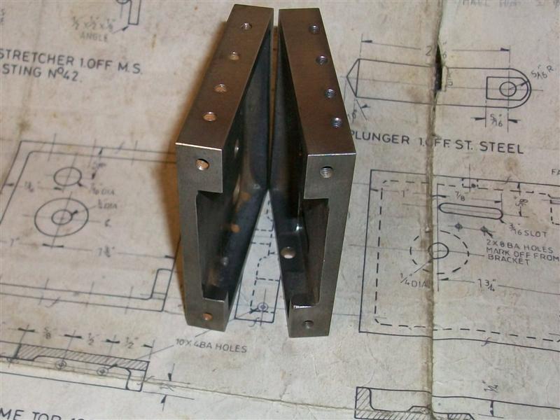
| The next parts I made were the two arms of
the pony frame and the associated stretcher. Both of these items were very
easy to make but I am including all the parts I've made for completeness.
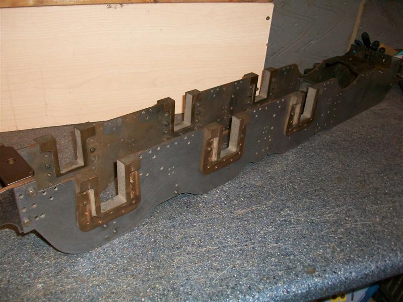
The pony frame arms are just an exercise in marking out followed by lots
of arm-ache and some swearing (or was it the other way round?). I started
with two plates of 3/16" black steel sawn to 11.1/8" x 3.7/16" and marked
out and drilled all the holes while the plates were still rectangular. Next
I marked out the profile and and then it was sawing, filing, sawing, filing,
sawing.....At least I managed to get the holes correct where they connect
to the mainframes. I don't know why I didn't use the CNC mill to profile
these at the time because it would have made light work of them. An ideal
job also for laser or waterjet. |
 |
| 2. Pony frame stretcher |
|
|
 |
The pony frame stretcher is four pieces of 1/4" x 1.1/4"
flat mild steel which I welded together and then milled to be a snug fit
between the two lots of frames, the width being set by clamping one of my
spacers close to the end of the mainframes. Then the fixing holes were marked
out and this time the holes are tapped 2BA so that bolts can be used to
pull the whole lot together. There is also a 3/8" reamed hole at the bottom
to take the pony truck pivot pin. The two cutaways at the front are to clear
the rear spring hangers on the mainframe. |
 |
| 3. Pump Stretcher |
|
|
 |
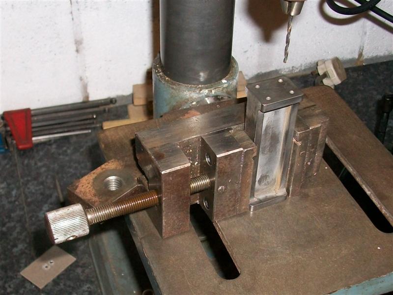
The pump stretcher is just a bit of 10 swg
mild steel plate and a couple of bits of 1/2" x 1/2" x 1/8" m.s angle. The
plate was marked out in the normal way and all the holes drilled, the only
awkward ones being the two 1" holes. The six pump mounting holes were done
using the co-ordinates from the Zeus book, a most useful reference book
in the workshop and a mine of information. I had a 1" blacksmiths drill
on a 1/2" shank but didn't fancy drilling this size from scratch so I used
a 24mm hole saw instead and used the 1" drill to open up to size. This was
done on a bit of 12mm MDF and I did make sure that the plate and MDF were
well clamped down on the table. I wasn't too worried about accuracy here
since the top hole is just clearance for some pipework and the lower hole
is for locating the pump body - I can machine the O/D of that to suit. |
| My steel angle had a bit of a ropey finish
so I cleaned up one outer face on the belt linisher and marked out one of
the rivet holes on that face, making sure that, once assembled, the angle
would be about ten thou wider than the finished size. I also marked out,
drilled and tapped the three frame mounting holes on the other face of the
angle. After dropping a rivet into the one drilled hole and clamping similar
to how I did the top stretcher, the other three rivet holes were spotted
through and drilled with the rivet going in each time. After messing up
some riveting once before by getting the holes slightly out of position
and having to open them up I always follow this procedure of drill, rivet,
drill, rivet etc. Once the assembly was completed, it was clamped to an
angle plate and the outer edges were skimmed on the mill to clean the faces
and end up with a snug fit between the frames. I may leave the pump out
when I see how well the injectors work but the pump stretcher can stay,
though, as it helps to stiffen the frames. |
 |
| 4. Drag Box |
|
|
 |
The drag box came as two identical castings which are machined all over but, strangely, not bolted
together. These could just as easily be made from cast iron or mild steel billets which would be a lot
cheaper although a lot of pocket milling would be required. It acts as both a stretcher for the rear
of the pony frame and a pivot point for the drawbar to connect the tender. It also contains the cylinder
cock bell crank assembly fixed to a machined area on the lower part and with a drilled hole on the upper part.
The first thing I did was to clamp each casting to an angle plate, squaring up as previously shown, and milling
the four edges to final size. |
 |
 |
Then they were loaded to a milling vice and the top was flycut and, as can be seen,
my flycutter was smaller than the workpiece. It matters not because these surfaces have no function and cannot be
seen once built up. Having a cleaned-up surface makes marking out of the holes easier, though, so I felt it worth
doing. Also, the inside face of the boss of each casting was flycut to finished height and the area where the bell
crank assembly mounts to the lower casting was machined flat. After this, all the holes were marked out and then drilled
and tapped as appropriate. The drawpin holes I drilled 15/64" and will drop a 1/4" reamer through them, by hand, after
assembly to get them in line. I chose to make this assembly a little different to the drawing. |
 |
 |
I made the crank arm as per drawing but didn't bother to make the fancy pin and braze it to the crank arm.
The picture shows the simplified parts that I made and the pin, which is just a bit
of 3/16" unhardened silver steel, just pushes through the side of the casting, through the spacer and the crank arm and
into the bearing. It needs nothing to keep it in place because the whole assembly is trapped between the frames. I made
sure that the parts were a reasonably accurate fit between the pony frames and also made sure that they were square otherwise
they would probably put a twist into the frame when I bolted it all together. I also noted that the tapped holes in the
sides of the top half are at different positions to the lower half. It would have been easy to assume they were symetrical
and just mark out both halves the same. |
 |
| 5. Pressure Brackets |
|
|
 |
The two rear pressure brackets help connect the rear beam to the pony frame and also carry
the hemispherical pressure pads which sit in the sliding cups on the rear crossbar of the pony truck. I used gunmetal castings
but I think I would make these from mild steel bar another time. They didn't need much fettling and it was just a case of
milling them square and doing the holes. |
 |
 |
Although the picture shows all the holes drilled, I didn't mark out those for connecting
to the rear beam. After bolting the dragbox to the pony frame and the rear beam to the dragbox I spotted through the rear
beam (which will be made next) to the pressure brackets behind. |
 |
| 6. Frames Stays |
|
|
 |
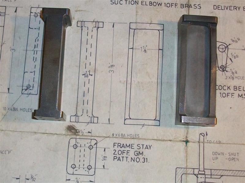
To ensure that the frames pull up true and square during
assembly, there are quite a few bits that all have to be the same size.
On Britannia there is the front buffer beam, the bogie stretcher, the long
top stretcher, the pony frame stretcher, two frame stays and of course the
horn stretchers. Because I used 3mm plate for the frames I needed to keep
the inside dimension between them at 3.395", held to a fairly close tolerance
although a couple of thou wouldn't be too bad. I had planned to make the
front buffer beam next but then realised I would need something to accurately
set the space between the steel angles used to fix the beam to the frames
so decided to make the two frame stays next. |
 |
 |
These are available as a casting but I chose
to make mine from mild steel bar. Then I spotted an old sash window weight
in my scrap box so that was used instead. I also decided to make a couple
of spacer pieces to help with frame assembly so the first job was to cut
off four billets. These were just cleaned up in the lathe and the ends faced
to finish length. After that it was just a case of milling away all the waste
and getting the general shape. Nothing here is important other than the
length and squareness. Final part of the job was to mark out the four holes
at each end then drill and tap 6BA. |
 |
| 7. Main Horns |
|
|
 |
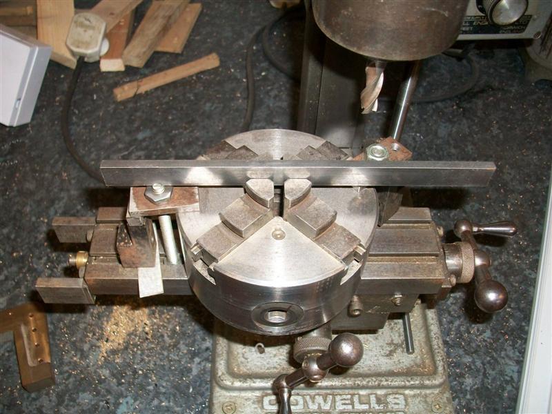
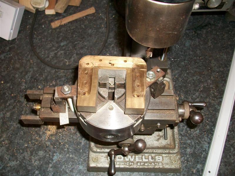
The main horns were supplied as gunmetal castings and
need machining all over, although there was not a lot of metal spare so
a little thought was needed to ensure a good cleanup. The important bit
is obviously the fit to the frames so I decided to try holding on the inside
edges. How I solved it was to use my self-centering 4-jaw chuck on the mill
which I first set up square to the table. By expanding the jaws, I was able
to get a good grip on the horns which allowed me to mill the tops and outer
edges of the flanges and the seating faces. These in the picture have been
finished but this is how I held them. |
 |
 |
Once I had a flat face and square edges, it was easy to
set up in a normal milling vice to machine the opposite side and drill the
holes. The trapezoidal edges were formed by using a sine bar and bolted
to an angle plate. The inner faces of the horns have yet to be machined.
There is only about twenty thou per side to come off and these may be milled
to size whilst bolted to the frames to ensure the axles are all parallel
to each other but I will need access to a larger machine for this. It was
at this point that the extra shaping was done on the frames to ensure a
snug fit for the horns. Here they are just held on with a couple of bolts
in each. |
 |
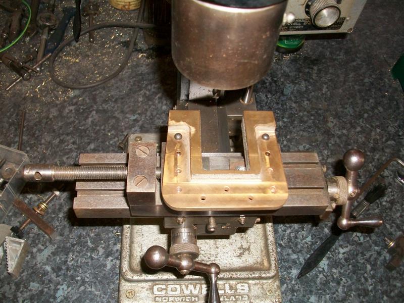
| I needed to think about milling the internal
bearing surfaces of the main horns and I considered it easier to make the
axle boxes to fit the horns rather than making the horns fit the axle boxes.
In an ideal world, I would plonk the mainframe assembly, complete with horns
bolted on, onto the bed of a Bridgeport, true it all up, load up a long-series
1" dia end mill and finish machine the whole thing in one visit. However,
using my little Cowells mill for something of this size is stretching the
envelope somewhat. I decided to try and use the precision milling vice to
grip the horns on the frame locating flanges but first I had to find a novel
way just to hold the vice because I ran out of y-axis travel if I mounted
it the usual way. Once I had worked out the best direction to work in, I
then loaded the first horn casting to the vice. They are all a good fit
to the frames and I would have no trouble with repeatability although to
help keep them square, I dropped a couple of large dia rivets through two
of the mounting holes to locate against the side of the vice. However, as
I tightened the vice the feel was wrong - too spongy - so I measured the
gap at the bottom of the horns, released the vice and measured again. I
was springing them closed by about seven or eight thou so this was no good.
I was also getting a slight lift from the moving jaw which was affecting
the squareness. |
 |
 |
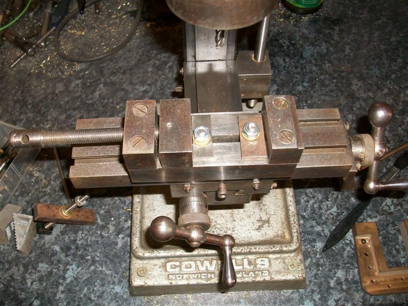
I decided to treat the vice as a fixture and just lightly nip the jaws
up and then use clamps to hold the workpiece down. It's getting a bit busy
on here now, and it's going to take quite a while to machine the six horns.
I was able to clock off of the outer edges of the external flanges to find
the centre line and had to be quite accurate on this because, even though
they are symetrical, three of the horns are mirror-imaged (left and right
handed) but I can't reverse my fixture so any offset from the centre line
will be doubled once the horns are reassembled. |
 |
 |
Now it was just a case of taking multiple passes up one side, across the top and down the other side
until I had about twenty thou left to come out side to side. I used a 6mm carbide end mill for this as any of my smaller
diameter cutters have too short a flute length and I was taking about ten thou per pass. The top didn't need so much material
removed and was finished during one of the earlier passes. Before making the final cut on each, I re-checked my centre-line
position and calculated the offset either side. The finish size is 1.500", the cutter is 0.236" so the offset is 0.632" either
side of centre, not forgetting to allow for backlash. And to finish the job off the corners were filed out once all machining
was complete and the horns bolted back into the frames. I checked them with 1.1/2" worth of mild steel and they fit OK but they
can be eased to suit with some emery on a stick once the axle assemblies are made if neccessary |
 |
| 8. Pump Body |
|
|
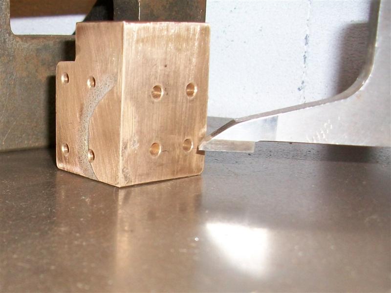
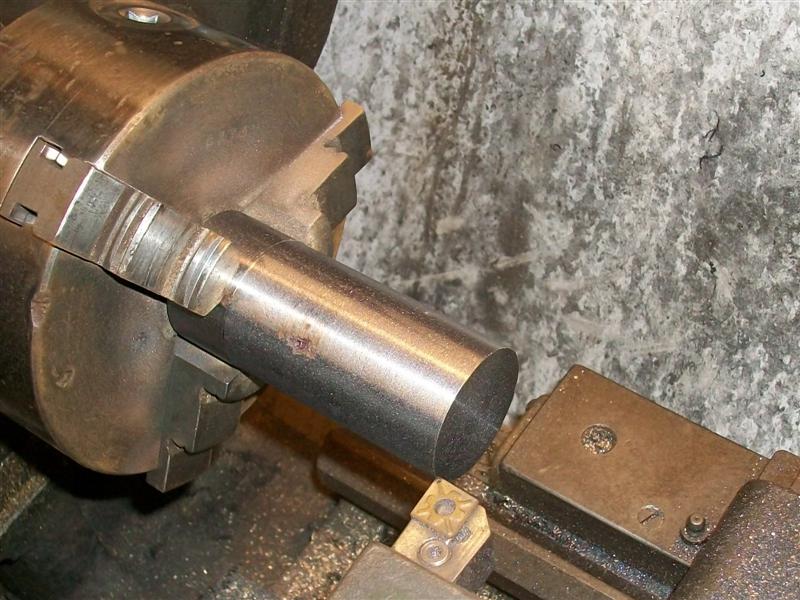
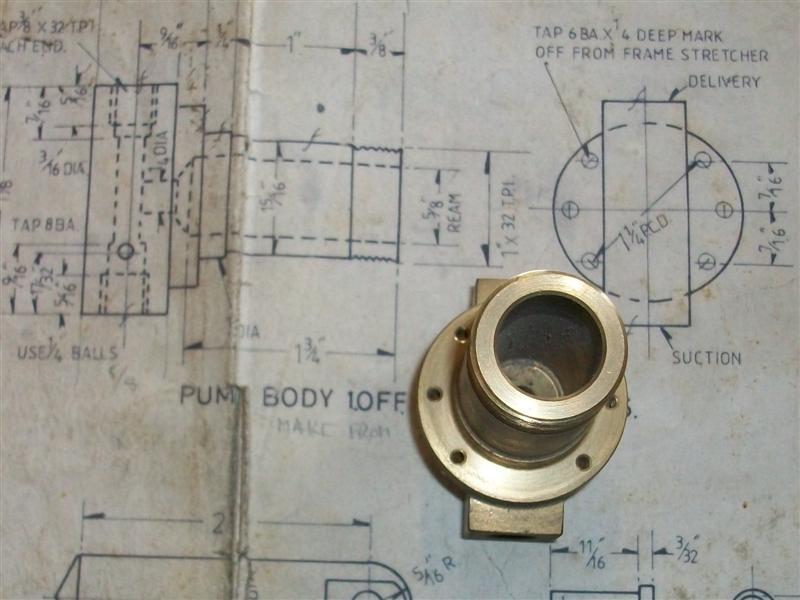
| Although the drawing calls for the pump body to be made from a gunmetal casting, I decided to
machine mine from 2" diameter brass since I had some in stock. The first alteration I made here was the smaller diameter of
the pump body. The drawing calls for a 1" x 32 tpi thread on the end with a 15/16" relieved dia along to the 1" diameter locating
spigot. To me, this is a nonsense and I decided to make the diameter 24mm with a M24 x 1mm pitch thread on the end. I will also
change the plunger to 16mm and use a 4mm section O-ring. After facing my billet to length, I held on the last half inch using
soft jaws in my 3-jaw chuck and did all the maching in one visit, starting with centre- and drilling the bore, drilling the small
hole at the bottom, turning the two outside diameters, reaming the bore and finishing with screwcutting the thread. For this, I
used a standard screwcutting tool with a 1mm pitch insert. The advantage of using an insert is that as soon as you see the outside
diameter getting a light skim then you are close enough to size to stop cutting and you have a full-form thread. When I originally
made this part, I had the luxury of an Ainjest high-speed screwcutting attachment on a Colchester Triumph 2000 so there is no
discernable run-out point but if making it on my simple centre lathe today, I would just create a decent length of undercut and
run into that. The length of thread is unimportant as long as it is long enough to allow the nut to screw on fully. |
 |
 |
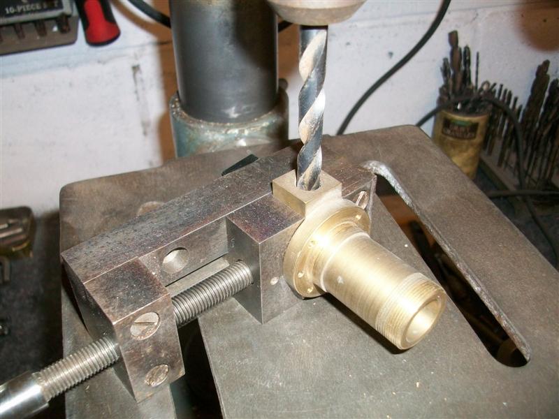
To form the back section, I held the part in a 3-jaw chuck
on the mill and machined the four faces to size. The suction
and delivery connections were made by holding the work in my normal milling
vice and drilling and tapping the first hole 3/8" x 32 tpi and then turning
the job over and doing the same again from the other side, bearing in mind
that the two holes are different depths. I also drilled the through-hole
at this point, being careful because I was breaking into the cross hole
that was drilled to depth while on the lathe. Final job
was to mark out and drill and tap the six mounting holes which are on a
PCD of 1.1/4". The drawing shows a distance of 7/16" between holes but this
is incorrect, the distance should be 0.442". When I made the pump stretcher,
I used the proper co-ordinates and have to do the same again here if I want
everything to fit! |
 |
| 9. Pump Nut |
updated - 10/07/2021. See below. |
|
 |
I made the pump nut, in one visit, from 1.1/4" diameter brass held in the 3-jaw chuck of the Colchester
Triumph and, once again, had the benefit of high-speed screwcutting. First, I drilled at 9/16" diameter to about 1" depth
and then bored it out to 0.635" to clear the plunger diameter of 0.629" (16mm). Next I bored it out to 23mm (the core size
of the thread) and finally created a 24mm diameter undercut, 3/16" long, at the bottom for the thread to run into. Using a
boring bar with a triangular tip meant I could do this all with the same tool. The "O" ring will sit in this undercut. Then
I screwcut the thread using a 1mm pitch insert and using the pump body as a gauge. Finally, the O/D was given a light skim to
clean up and the nut parted off. I haven't put the 6BA tapped holes in yet, they're only for locking the nut to the body. |
 |
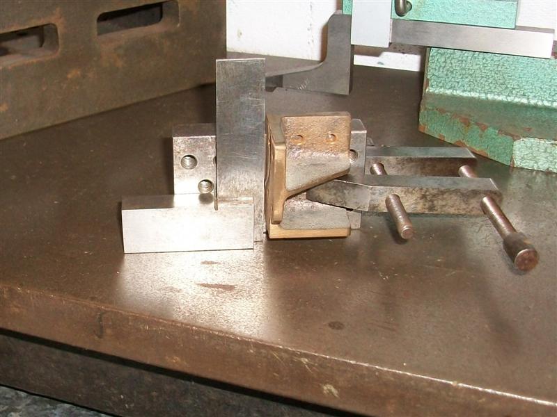
The plunger is just a bit of 16mm stainless steel with some simple machining applied to it. Here is a
picture of the pump assembled on its stretcher and fitted between the frames. The pump strap and eccentric will be made
after I have made the main axles. If I was making this assembly with the machines I have today, I think I would make
an M24 (or imperial equivalent, say 40 tpi) tap out of a bit of silver steel and make the nut first, tapping the thread.
Then I would make the body to suit the nut. This is because screwcutting upto a shoulder in a blind hole can be a bit daunting. |
 |
 |
11/07/21 - During testing, there was a leak
from the pump plunger. The "O" ring in the bottom of the nut obviously
wasn't good enough on it's own. I dismanted the pump and machined an "O"
ring groove at the front of the plunger and fitted a 7/16" x 5/8"
"O" ring. The groove was made using a 2mm wide grooving tool with
a second cut fifteen thou further along, touching on and plunging eighty
eight thou deep (0.176" on the diameter) and, once reassembled, withstood
130 psi without leaking anywhere. It is also very awkward to get access
to the pump for any sort of servicing. I had to remove all the brake linkages
and two horn stays as well as the pipework. This could do with a redesign. |
| 10. Pump Eccentric |
|
|
 |
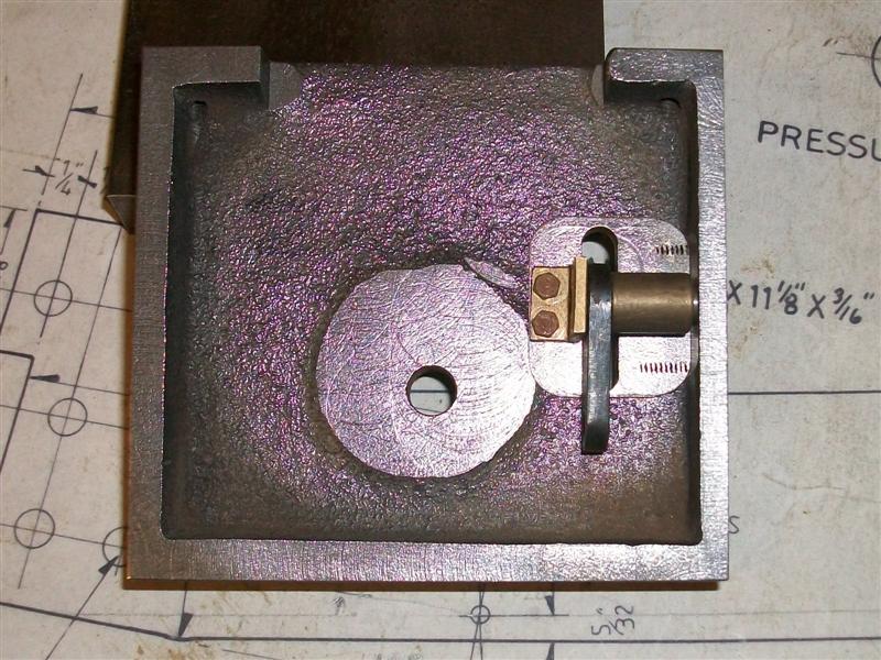
With the pump eccentric my first instinct was to face, turn and form the groove as one operation followed
by loading to the four-jaw independant chuck and machining the bore and boss as a second operation. However, I felt that I
would likely damage the shoulders of the eccentric with the amount of work needed on the second op so I decided to do it in
three stages instead. Starting with a 1" long billet of 2" diameter mild steel, I faced the back to clean up and skimmed
the O/D to 1.7/8" diameter by 1/2" long, then turned it round and faced it to 7/8" overall length. This meant I could load
the billet to the four-jaw chuck and tighten it up firmly with little risk of damage. |
 |
 |
Next, I marked out the middle of the offset and centre-popped
it followed by loading to the four-jaw chuck and, since I didn't need a
high level of accuracy here, true-ing up with a hard centre in the tailstock.
Then it was a straight-forward matter to drill and bore the 3/4" diameter
hole and turn the boss to 1.1/4" diameter by 7/16" long. I don't have a
3/4" reamer so boring would have to do. It's locked to the centre axle with
a couple of grub screws, anyway, which will pull it square to the shaft.
The last job on the lathe was to hold the boss in the four-jaw chuck and
true up the outside before machining the bearing area of the eccentric.
For this I used a parting tool slightly modified with a notch ground out
of the middle. I did, however, play around with two saddle stops to control
the width as I didn't want the fit to be too sloppy. To finish, the eccentric
needs to have the two drilled and tapped holes in the boss, which I have
made M6 because I have grub screws that size. I decided to mount a piece
of 3/4" diameter bar in a vee-block and clamp it on the drill table. |
 |
| 11. Bypass Valve |
|
|
 |
The bypass body has been made from 1/2"" diameter brass
stock, drilled 7/32" dia through and tapped 1/4" x 40tpi for a half-inch
length. The outside was turned and threaded 3/8" x 32tpi for a gland nut
with "O" ring. The body was reversed in the chuck, drilled 1/4" dia until
it met the thread then a 3/8" x 32tpi bored and tapped to take the return
pipe fitting. A hole was drilled and tapped in the side and a threaded nipple
soldered into place. Finally, the mounting plate was soldered to the body,
taking care with the orientation. The valve spindle was made from 1/4" dia
stainless steel, turning the front to 7/32" rather than the size shown on
the drawing. Then a 5/8" long section was threaded 1/4" x 40tpi. After parting
to 3.1/4" long, the part was reversed in the collet and the end turned and
threaded 5BA. Next, a further section was turned to 3/16" dia for a short
way and the workpiece taken to the mill. Holding on the 1/4" dia, four flats
were milled to 5/32" A/F. Finally, back to the lathe and the rest of the
spindle turned to 3/16" dia. |
 |
 |
I've made my outlet different to drawing to suit the 1/4"
dia pipe that I'm using. A piece of 1/2" dia brass was turned and threaded
3/8" x 32tpi to screw into the botton of the valve. A 3/16" dia hole was
drilled through and a small 45 degree chamfer made in the bore. Using a
mandrel, the flats were done on the mill but I missed a trick by not using
hexagon stock. A 1/4" counterbore was drilled in the bottom and a short
length of 1/4" copper tube silver-soldered in. Finally, a spindle gland
nut was made from 7/16" hexagon stock with a 3/8" x 32tpi thread and 1/4"
dia hole through, and a small operating handle made. Off-the-shelf pipe
nuts can't be used because the hole is too big. A 1/4" x 1/32" section "O"
ring finished the job off. The outlet tube will be adjusted to suit whatever
arrangement I use to return water to the tender. |
 |
 |
09/01/20 - I couldn't get the return pipe to work, it
kept fouling the pony truck. In the end, I remade the bottom fitting from
some hexagon brass, drilled blind and cross-drilled 3/16" dia and counterbored
to take 1/4" dia copper pipe. Two pieces of pipe were silver-soldered
to create the right-angle using 40% solder, then the assembly joined together
with 55% solder. The pipe connector on the end is covered under drawing
15. |
 |
| 12. Next Item... |
|
|
| |
|