| Drawing 22 - Tender WPU Gear, Steps, Brake
|
| 1. Brake Hanger Brackets |
|
|
 |
I have made the brake hanger brackets from 1" dia brass
bar but because they are inside the frames and completely out of sight,
I have changed the design to ensure that the bracket carries the brake hangers,
not the shouldered bolt as designed. On the drawing, I have pencilled in
an extension to create the pivot point. As with the spring hangers, the
holes were drilled first and the work supported on pins to mill the outer
form. I have also done away with the as-cast shaping in favour of simple
turning, followed by counterboring clearances for the nuts to fit on the
fixing screws. The spigot is turned to 6mm dia and just over 1/8" long,
and the hangers, which are from 1/8" material, have a 6mm reamed hole to
match. A simple screw and washer will retain them. |
 |
| 2. Brake Hangers |
|
|
| The brake hangers have been made from 5/8"
x 1/8" EN3B bright bar and I have changed quite a lot of the dimensions.
I started by cutting the material 1/8" longer than drawn because I have
increased the hole sizes and made the outer dimensions to suit. All the
holes were marked out then drilled and reamed 3/16" diameter, although the
upper hole was opened out to 6mm later. A pair of 3/8" dia filing buttons
with 3/16" stems were made and these were used to help produce the forms
at the ends and also to act as filing guides for the centre hole. A small
amount of roughing out was done on the mill but most of the shape was hand-filed |
 |
| 3. Brake Beams |
|
|
 |
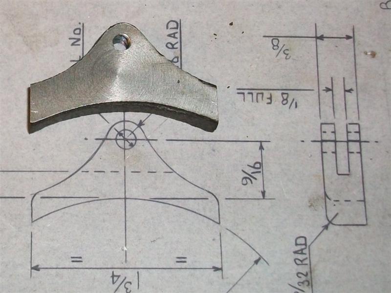
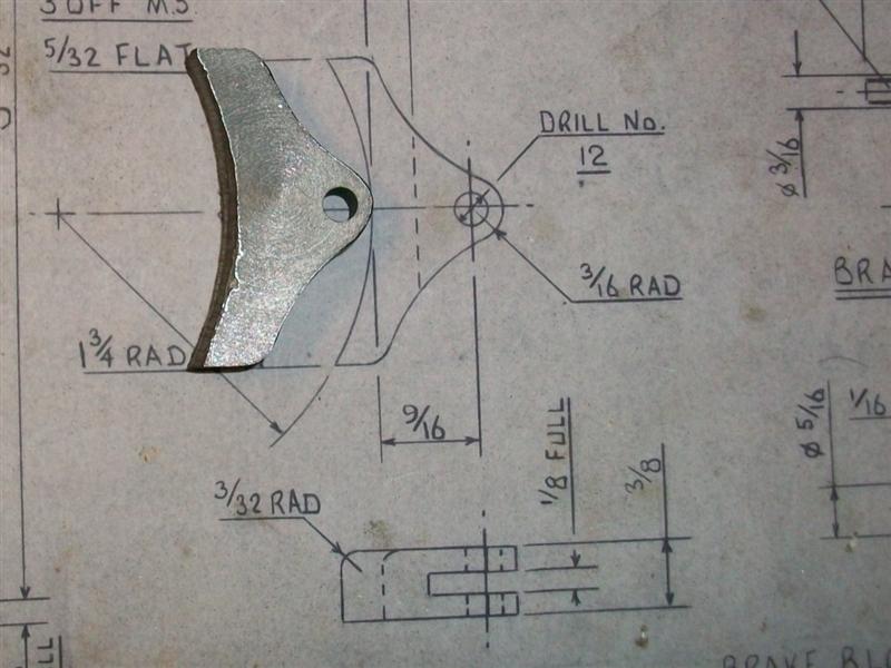
Rather than make new ones, I modified a spare set of loco
brake beams to fit the tender. I don't like shoulder bolts as I find they
are prone to break at the root of the thread so I designed the brake beams
to be spigoted, with a 4BA tapped hole at each end for retention similar
to the brake hanger brackets. I had to adjust the lengths to suit what I
was planning and this is when it became obvious that the draughtsman had
made numerous mistakes which could have resulted in a load of scrap work.
Each beam was held in the independent 4-jaw chuck and he spigot turned to
3/16" dia and a tad over 1/8" long. At the same time, they were drilled
and tapped 4BA. When assembled, the hangers will be retained by simply screwing
in a short 4BA bolt to full depth. |
 |
| 4. Brake Blocks |
|
|
 |
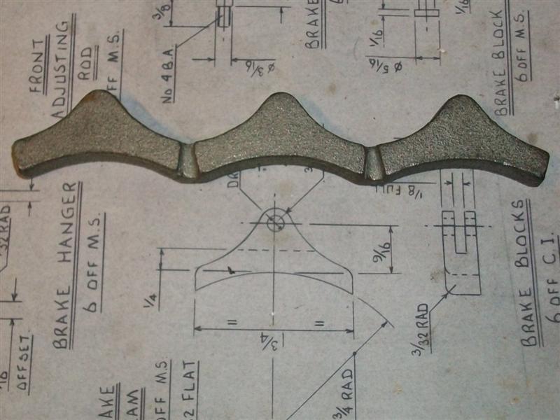
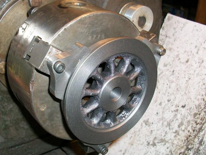
These are the brake blocks, as supplied, cast in threes.
First, I cut the blocks into individual pieces and marked out where I wanted
the brake pin hole to be in each blocK. The hole size in my blocks is specified
as 3/16" so I drilled and tapped these holes at 2BA, this being the largest
thread that is SMALLER than the finished hole (you'll see why in a minute).
The next job was to face front and back of the blocks for a flat and level
finish. Facing off in the lathe seemed the easiest way so a means of holding
them was needed. Because I have soft jaws for my chuck, I made a carrier
plate onto which I could bolt the brake blocks and then load to the soft
jaws. |
 |
 |
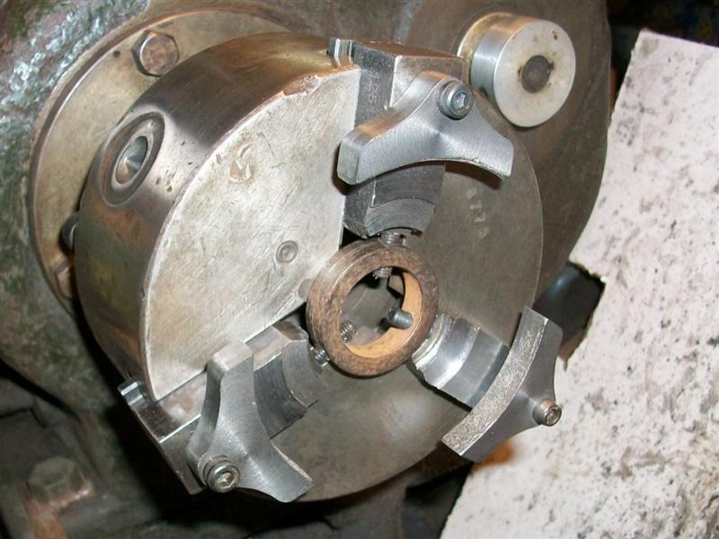
I happened to have a mild steel blank of 1.7/8" dia x
1/4" thick but any old bit of steel would do. After facing off and turning
a dia for trueness, then reversing and facing the back, I have drilled a
2BA clearance hole in it to mount the brake block, bolted from the back,
and also added an anti-rotation pin to hold it firm against the cut. Once
both sides were faced, the next thing was to get the length of the block
machined which I did in my small milling machine. Each brake block was placed
in the vice using the bottom slot of the vice to centre it and then aligning
the block by eye. There will bound to be a more accurate way but I don't
think it matters that much. |
 |
 |
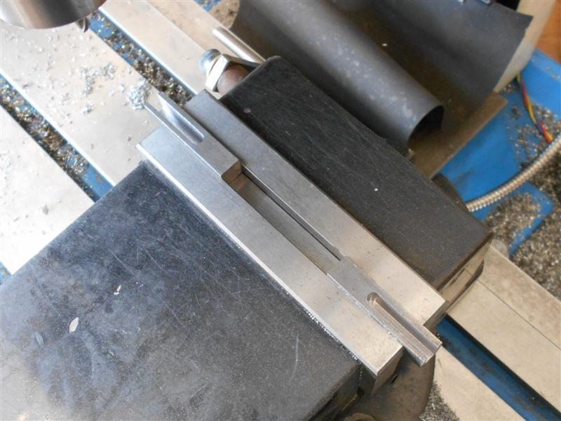
Because the width of my vice (1.618") is less than finish
size of the brake blocks (1.750"), I was able to mill one side to size (0.066"
from side of vice) and then do the other side to finish at the required
size. Next I had to clean up the outer edges of the brake blocks so it was
time to open the tapped holes up to their finished size. One of mine was
a bit adrift so I opted to mount the blocks in the vice, holding on the
milled flats, and use a 3/16" slot drill to align the holes more accurately.
Some of the blocks have a slight witness of the thread but it's not important
- there's a pin through there on assembly. |
 |
 |
I had forgotten to take a photo at that point ,so that
last picture was taken at the end. Most castings have a draft angle and
I bolted mine together in pairs with the smaller faces together and then
started to clean up the profiles using a carbide burr in my hobby drill... |
 |
 |
...and finishing off with a small drum sander for the
internal radii and my belt linisher for the external radii. |
 |
 |
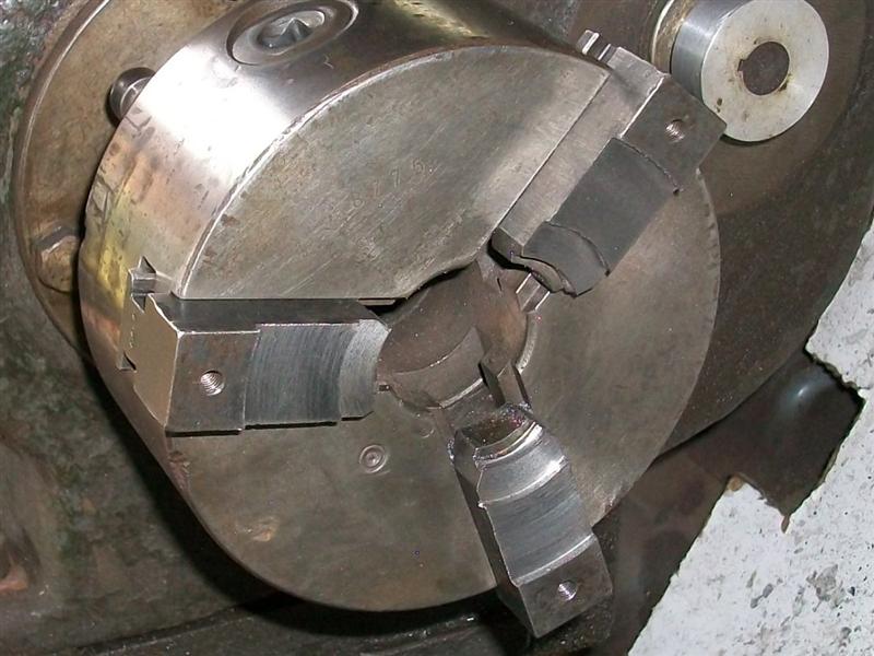
That only left the wheel-form part of the job to do and
the slot. Using the same soft jaws as earlier, I drilled and tapped a 2BA
thread in the top of each jaw and loosely bolted three of the blocks to
the jaws. Then I gently clamped the jaws onto a finished wheel to align
them and finally pulled the bolts up tight. I used cap screws because they
are normally high-tensile and you can get them good and tight. |
 |
 |
Then I wound the jaws down onto an adjustable ring (normal
soft-jaw accessory) to leave about thirty thou to come out. I also set the
compound slide over to about two degrees to enable putting a slight taper
on the blocks. I would have liked to have included some sort of anti-rotation
pin to the setup but decided that all would be okay with small cuts and
a gentle touch. I took five thou depth of cut from the cross-slide and used
the wheel as a gauge. Once to size, I used the compound slide to take a
final cut to match the wheel profile. The brake blocks are symmetrical so
no special attention has to be paid to orientation, unlike the loco blocks. |
 |
 |
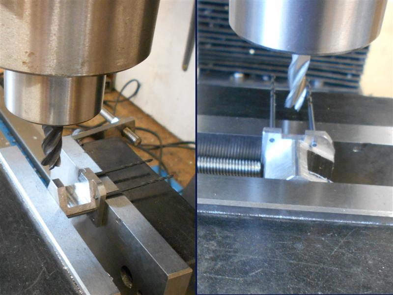
Finally, it was time to put the slot in. I don't have
much in the way of slitting saws so opted to mill them out using a 1/8"
slot drill (of which I have plenty). However, they are not deep enough so
I freehand ground a bit of the shank down and milled the slots in two hits,
saving my home-made long-series slot drill to finish the depth. |
 |
| 5. Brake Linkages |
|
|
 |
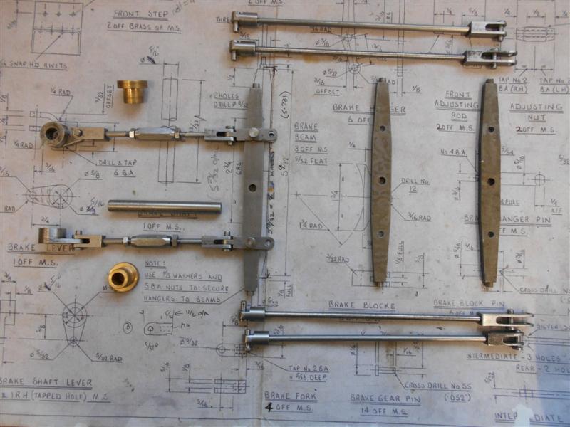
There is quite a collection of parts that go together
to actuate the brakes. I have made a couple of variations to the drawings
to suit my tooling; the rods are all threaded M4 and the eyes have been
replaced with threaded bosses so that I can adjust for any variation in
the brake block sizes. With the forks, I prefer to make the slot first,
milling to within twenty thou or so of the bottom, then removing the underneath
support and finally plunging the slot drill through at the end of the slot
and working outwards till the cutter breaks free. This prevents the cutter
grabbing the work and bending it inwards. |
 |
 |
Next I drill the cross-holes using packing
to stop the part collapsing, and finally to mill away the opposite end if
it's double-ended or drill and tap through on the lathe in the 4-jaw chuck
if it's a rod end. There are two of the adjusting linkages, three components
needed for each one or five if one counts the forks but the drawing only
calls for one set. I have used M4 right-hand and M4 left-hand to create
the adjuster. |
 |
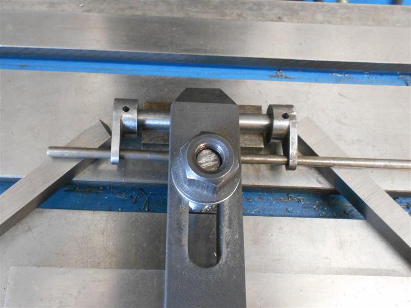
The other variation I have made is how I fix the brake
shaft levers to the brake shaft. The drawing suggests a 6BA grub screw but
I felt this was far too flimsy and have pinned mine with 3/32" taper pins.
To set up the drilling, I mounted the shaft in a tiny Vee-block on the milling
table. I only set it by eye, not worth getting the wobbler out for, but
a quick check with the old ruler trick seemed OK |
 |
 |
They were then set up with a bar through the eyes and
resting on parallels to make sure they were level and the holes were then
drilled with a 3/32" dia drill as pilot followed by the taper drill. For
any who have not used taper-forming drills before, you need to be aware
that they have a tendency to grab the material and pull themselves into
the hole, resulting in a stalling of the drill for larger sizes (and probable
damaged workpiece) and a broken drill for smaller sizes. It is very important
that one uses a short, sharp pecking action to keep breaking the cut when
using these drills. And they need to be held extremely tight in the chuck. |
 |
| 6. Tender steps |
|
|
 |
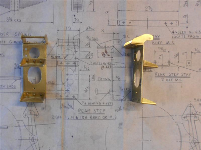
The front and rear tender steps are both made from 20
swg brass sheet and are fairly simple affairs. After cutting out the the
main upright section, the two large holes were drilled and then filed to
size and shape. This was followed by drilling eight 1/16" dia holes for
the rivets holding the treads, the single hole for the bracing stay and
the three holes for fixing to the platform. The treads were marked out,
cut to shape and the treads dimpled with a centre-pop. The two outer holes
were marked out and drilled 1/16" next and finally the tread sides and rear
were bent. The treads were riveted to the uprights and the other two holes
in each tread drilled through and riveted. The rear steps were made in a
similar fashion, the main difference being the hand-hold at the top of the
steps. The handrail is a piece of 3/32" dia brass bar turned at each end
to 1/16" dia and set in place using the natural spring of the material to
retain it. The mounting holes beside the top large hole need to be left
hand side and right hand side respectively. Otherwise, the steps are symetrical. |
 |
| 7. Brake Adjustment |
updated 26/04/20 |
|
 |
While setting up the tender brakes, It became obvious
that a better means of adjustment was required if they were to function
effectively. I decided to make four more turnbuckles and set them between
each of the pull rods. As before, these were made from 3/8" hex mild steel,
one inch long, drilled 3.3mm through and tapped M4(RH) at one end and M4(LH)
at the other. The pull rods were cut and 5/16" removed from the longer half.
This effectively meant that I had adjustment of the brake on each wheel.
I have also settled on how to operate the brakes. First, I made another
lever arm to mount at the centre of the brake shaft and a bracket to fix
to the underside of the bottom plate. This bracket has a slot to allow adjustment
and a pin to hook a strong spring to. |
 |
 |
I'm not modelling the handbrake system as drawn, it relies
on the tender chassis and it's tank being permanently joined. I do, however,
want a handbrake and have knocked my own version. It relies on a strong
spring to hold the brakes on when in the steaming bay, for instance, but
a cam operates against a lever to free the brakes for normal operation.
I also wanted a means of clipping the extra water pipes to the chassis and
the picture on the left shows milled cutaways for the 1/4" pipe in the new
crossbar. These are for the handpump and the axle pump return. A little
gearbox was made to move the operating point to a location clear of the
wheels. The gears came from the "useful one-day" box. |
 |
 |
This view on the left shows the cam with it's locking
flat, the position that holds the brakes off. The spring is an old bed-frame
spring. The final view shows the thing assembled with the pipes in place
and a T-bar Allen key poking through a hole in the side of the tender chassis.
Once the turnbuckles were adjusted up, it works well and holds the tender
on a five degree incline. No chance of rolling off the rails in the steaming
bay. |
 |
| 8. Spring Hanger Brackets |
|
|
| There are castings available for the tender
spring hangers but I felt they made an interesting little project to machine
from solid bar. Twelve are required and this lends itself nicely to some
sort of production-line technique. Material is unimportant and I have chosen
to use EN1A mild steel. On the drawing, I measured the minimum dimension
needed to make the parts from round bar and it appears that 1.1/16" dia
would suffice. I had 1.1/8" dia in stock and twelve billets were cut from
this and faced to the given length of 13/16". I have transposed the circle
onto the drawing to determine the best way to mill the rectangular shape,
and have added dimensions that are either scaled or calculated to help with
this. This is the starting shape. |
 |
 |
Next, I drilled the four mounting holes,
and an extra hole not shown here (explained later), 1/16" dia x 3/16" deep.
The billets were then turned over and the three front holes drilled, not
as drawn but also 1/16" dia and by 1/4" deep. The holes are for dummy 10BA
bolts so can be opened out later and the bolts set with adhesive or tapped
with very little effort to give a shallow thread. I didn't fancy having
to thread thirty six full-depth holes with all the inherrent risk of tap
breakage when it is unneccessary. |
 |
Drilling the holes at the start made it easy to do the
subsequent milling operations and the first of these was to machine the
upper angled faces. I had calculated that I wanted 0.085" from the edge
of the holes to the outside, seen on the drawing in the picture above. Using
two 1/16" drills, the hangers were set in vice and the cutter just touched
on to one of the drills. the DRO on the quill was zeroed, the quill lifted
by 85 thou and the DRO re-zeroed. Now I was able to mill the whole of the
top profile. Using a single drill, I then set the hangers at various angles
to rough out the radius at the top and these would be finished with a file. |
 |
 |
The back of the vice had been set as the "Y0" zero datum
and by working down to the "Z0" depth and to the calculated "Y" position
each time, there was no need for a workstop on the "X" axis and the rear
inner face was blended as work progressed. Next, I machined the shape of
each of the lower sides in turn. I calculated that the angle should be twenty
five degrees but I didn't have two holes avaiable to copy the earlier operation
so an angle block was used in conjunction with a single locating pin. The
workstop is being used to prevent the angle block moving whilst setting
the workpiece into the vice but location is unimportant. |
 |
 |
Since I'm still using the same cutter, the "Y" dimension
stays the same as does the quill setting of zero. Once all twelve were done,
the angle block was reversed and the stop moved to the other side of the
vice. The other sides were now machined to size. In a similar manner, the
spring housing was cut away next followed by the necking on the sides of
the brackets, using 10mm and 6mm dia cutters respectively. |
 |

|
Then it was time to create the lower shaping and this
is where the extra hole came in. When I realised what was needed, I went
back and drilled the extra hole in all twelve, it needing to be 112 thou
up from the base, or 0.763" from the top, and on the centre line. This was
drilled 3/16" deep to ensure it didn't break through, but would probably
be hidden by the spring if it did, so maybe not too important. So, once
again, I was able to support the work on pins and create the required shape
and was also able to take a little off the front section. Finally, I set
a workstop and reloaded them on two pins to enable drilling and tapping
of the 6BA spring-mounting holes. From this point on it was all hand-work,
filing and linishing the radii. |
 |
| All that is required now is some time spent
polishing them, and fixing the dummy 10BA screws into the three face holes.
I have made these to conform with the Warnett drawing but, as a colleague
pointed out a while back, they don't look much like the prototype except
head-on. However, they could be machined further using the same system by
milling away material on top and at the sides to create a more authentic
look but that's a detail too far for me. This has been quite long-winded
but I was hoping to demonstrate that, by drilling the holes first, all the
subsequent operations became so much easier. And when there are twelve to
make, this style of manufacture is quite efficient. |
 |
| 9. Tender Springs |
|
|
 |
The springs should have been gunmetal castings
but aluminium ones have been supplied instead. Because of this, I have made
a modification to the item by using a brass liner in the spring housing.
There was just enough room to drill and ream a 7/16" hole in each and press
in the liner. The other parts are as drawn and quite straightforward. I've
cleaned up the area of the buckle and filed the underside of the springs
but I'm not particularly impressed by the quality of these castings and
may consider binning them and making real ones once I have seen them painted. |
| 10. Next item... |
|
|
| |
|
|