| Drawing 6 - Pony Truck
|
| 1. Pony Truck Horns |
|
|
 |
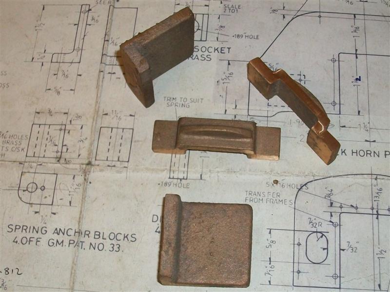
The pony truck horns are made up as left-hand and right-hand
assemblies and include the front and rear horn plates, the horn blocks,
horn stays, spring anchor blocks and spring guard amongst others. The only
castings used in this part are the horn blocks and the horn stays which
are made of gunmetal, all the rest is fabricated. I started by splitting
the castings into the four horn blocks and machined these all over in the
milling machine, all very straightforward work with the flycutter. The base
of the horns were drilled and tapped 4BA and the holes in the sides to enable
the riveting together of the assembly were marked out and drilled 1/16".
The horn stays only need the mating surface machined and this was flycut
in the same manner although I also cleaned up the side faces and the bolting
face. These were then marked out and the 4BA clearance holes drilled. |
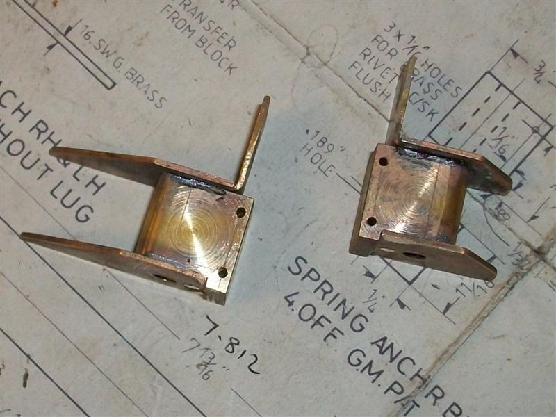
| I made the front and rear horn plates out of 16swg mild
steel sheet and have added extra fixing points for a bit more robustness.
Because I am using the front casting, I have also drilled holes for screwing
the backplates to it. The spring anchor blocks are just a couple of lumps
of brass milled to size and their top and bottom plates made from some 16swg
brass sheet. All the rivet holes are 1/16" and the home-made rivets are
just some 1/16" dia brass bar cut to length. Assembly has been a bit tricky
because of the need to get the horn blocks in the right place and keep everything
square. The holes on all of the parts were marked out and centre-popped
with extreme care and then drilled and countersunk. To make life easier,
I decided to solder the spring anchor blocks and the respective top and
bottom plates together. |
 |
 |
For this, I used solder paint and then riveted the parts
together, using a 4.8mm drill shank in the spring pin hole to aid alignment.
Once riveted, the drill was removed and the assembly heated until the solder
flowed and finally left to cool for a while. Next I riveted the axlebox
guard, just a piece of 3/16" brass angle, to the top of the front plate.
Although not on the drawing, I added an 8BA hole in the back of the spring
anchor blocks and a corresponding countersunk hole in the backplate so that
I could also bolt them together and then riveted the front plate, backplate
and spring anchor block assembly together. |
 |
 |
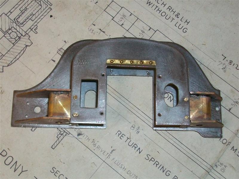
The final job on this sub-assembly was to rivet the horn
blocks into place. A couple of the holes needed clearing with the 1/16"
drill so a rivet was pushed through the top part and the horn stays bolted
on to help keep position prior to running the drill through the other three
holes. Then all the rivets were hammered up and the whole lot treated to
a bit of filing. I also need to dress the horns to suit the axle boxes because,
during marking out, I deliberately set the horns to be a few thou tight |
 |
| 2. Front Section |
|
|
 |
The pony truck can be fully fabricated but there is a
cast iron casting available to make the front part which I have chosen to
use. There is very little machining on this but it does need filing or milling
to the correct width to allow the back horn plates to be affixed. The hole
for the pivot bush was marked out 5.9/16" from the flat back face of the
casting but the side-to-side position was just judged by eye. This was then
drilled using a 3/8" dia drill followed by a 3/4" diameter drill, although
the drawing calls for 7/8". There is also the pivot bush to be made and
I have made this from 1.1/8" dia brass, turning the O/D to a touch over
3/4" diameter for a press fit into the casting and then drilling and reaming
a 1/2" hole through the middle prior to parting off. This was then pressed
into casting. |
 |
 |
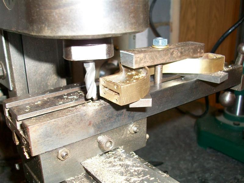
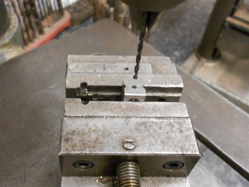
The side faces where the back horn plates bolt to were
machined on the lathe by mounting the frame as shown in the photo and the
holes were spotted through from the horn plates prior to drilling and tapping
8BA. I shall use countersunk screws to fix the horn plates to the front
frame. The final section that needs attention is the cutout where the centre
brace fits to and this was left for the moment as I will file it to depth
after I have made the centre bracing bar. |
 |
| 3. Rear Beam |
|
|
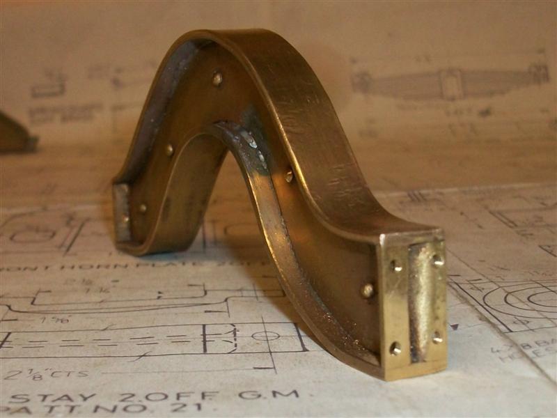
| The rear section of the pony truck is fabricated
from 16swg brass sheet and forms a hollow box section. The top plate carries
the pressure plates which allows the truck to move laterally and the inside
of the box section carries the return spring bar which is used to return
the truck to a central position. I have chosen to make mine differently
to the drawing and made two side and end pieces, a top plate and a bottom
plate. I have also made the centering bar bushes more like the actual rather
than what has been drawn. After cutting the two strips of brass that form
the sides and ends, I marked out and drilled all the holes in the ends before
bending to right-angles. These were then dressed for length and soldered
together to form the section shown below. The top and bottom plates were
also finished to size with the slots drilled and filed to size, the bottom
plate having the longer slot. |
 |
 |
I have soldered the top plate into position but have left
the lower plate for now because I need access to the inside for setting
the springs either side of the centering pin. I also made the centering
bushes with their more authentic shape, just a bit of simple turning followed
by milling the shape of the base and drilling the four 10BA bolt holes and
the spring return bar to fit them which I have modified to suit. I have
made the pressure pads from a length of 1" x 3/16" flat brass bar which
I hacksawed off at 1.3/8" long and then milled down to 7/8" wide. Next,
I marked out the mounting holes and drilled them 6BA clearance and also
made up a filing button to help me form the outside semicircles at each
end. I had started to mill out the inside form but then realised it would
be smarter to get the outside finished first. |
 |
 |
The inside was just milled out freehand using a 1/4"
dia cutter and nibbling away at the ends to get an approximate curve of
3/4" diameter. It's not that important since, once assembled, they cannot
be seen, and the pad cups that ride in the channel can never reach the ends
anyway. They were then placed on the rear beam and spotted through, the
rear beam was drilled and tapped 6BA and the pads were then bolted down
with 6BA countersunk brass screws. Offering up the whole assembly to test
the fit, I found that the cups were fouling the sides of the pressure pads
near the extremity of travel and riding up. The simple answer was to skim
twenty thou off the outside dia of the cups and after that, they slid side-to-side
perfectly. |
 |
| 4. Centre support stay |
|
|
 |
Another part I have made is the centre support which bridges
the axle and is fabricated from 16swg brass sheet, soldered and riveted
together. It isn't exactly to drawing but is close enough as it will never
be seen once the loco is assembled. I made a tracing of the inside shape
directly from the drawing and added an extra 1/4" each end to allow
for bending. I also marked out and drilled the 10BA tapped holes in the
end sections since these will be spotted through to their mating parts.
After the ends were bent over, making a left-hand and a right-hand component,
they were clamped together and the rivet holes drilled prior to riveting
together. |
 |
 |
I didn't get the overall length exactly right but it doesn't
matter as it is easier to make the adjustment on the front casting. The
top and bottom strips were now formed over and under the bridge and when
they were a nice fit, I clamped the ends and soldered the whole lot together.
Finally, the ends have been given a very light pass with a milling cutter
to make sure they are parallel. |
 |
| 5. Wheels & Axle |
|
|
 |
The pony truck wheels were made in the same way as I made
my main wheels (see drawing 3 for a full description), that is using soft
jaws in my 3-jaw chuck. First op was to hold on the tyre, face the back,
drill bore and ream the axle hole and skim the O/D of the flange. All subsequent
opeations were done holding on the flange until the wheels were finished.
The axle was also done in a similar fashion to my main axles and again I
used EN8DM material. However, they don't need quartering so there are no
keyways to worry about. I had made them a light press fit but one side was
a tiny bit undersize and the wheel went on far to easy, so I employed a
trick from my production engineering days which was to knurl the bearing
diameter with parallel knurls. I only use caliper knurls on my lathe because
they don't put anything like the stress of pressure knurling on the headstock
bearings. |
 |
| 6. Axlebox and Covers |
|
|
 |
There are gunmetal castings available to make the axle
boxes but, as with the main axle boxes, I have made mine from 2" diameter
mild steel billets. The back face was first cleaned up on the lathe using
the 3-jaw chuck and a 7/16" hole drilled through before the billet was then
reversed and loaded to soft jaws with all other turning operations completed
in one visit. Using a small boring bar and using the compound slide for
varying the depths, I faced the front to length, finished the bearing bore
to size and depth, bored the bearing relief at the bottom and finished the
17/32" hole through. I aimed for a light press fit on the bearing bore.
Then they were milled to size the same as before |
 |
I have made the axlebox covers from some mild steel flat
bar. The edges were milled to size on the Cowells mill and then the front
faced off in the lathe with a small hole to locate the "Timken" covers followed
by reversing and turning the spigot for the bearing bore and the bearing
relief. Finally, the edges were rounded off on the linisher and the 8BA
clearance holes marked out and drilled. The "Timken" covers are
just held in with two-part resin adhesive. |
 |
| 7. Suspension |
|
|
 |
Realising that I had yet to complete the pony
truck suspension, I decided to get that finished before continuing elsewhere.
As with the bogie springs, I will replace these with proper springs at some
point in the future but, for now, I will use the supplied castings. There
are only a few parts needed to make the suspension - the cast dummy springs,
this time in gunmetal, a couple of spring bolts with cross-pins, the spring
plunger to carry the coil spring, the spring sockets that rest on top of
the springs and the spring guard for over the top of the springs. The springs
were held in the milling vice and cleaned up the top and bottom using a
16mm dia end mill before moving to the drill and putting the hole in them
to guide the spring plunger. After drilling 5/16", I ground a spare drill
and made the hole flat-bottomed as drawn, but it probably wasn't neccessary.
The spring bolts were made from some 3/16" mild steel, threaded 2BA at one
end and parted off. The drawing calls for 3/32" cross pins but they looked
too chunky to me so I used 1/16" material instead - panel pins, actually
- and I made a simple drill jig from some spare hex bar to help put the
cross-holes in. |
 |
The spring plunger was some 5/16" brass, drilled 6.4mm
to accept the coil spring and parted off at 5/8" long, the spring guard
was made from some 24 swg brass sheet and the spring sockets were made on
the lathe by drilling a 4.9mm hole through some 3/8" square mild steel and
parting off at 3/16" followed by milling on the side chamfers with the Cowells.
I also put two together in the small milling vice and drilled a 1.9mm hole
to produce the recess for the cross-pins and then just linished the underside
of each so that they sat nicely on the springs. |
 |
| 8. Next Item... |
|
|
| |
|
|