| Drawing 19 - Footplates and Details
|
| 1. Footplate Brackets |
|
|
 |
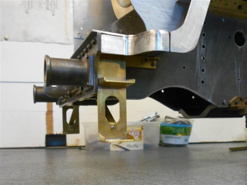
As drawn, the side footplate brackets have the holes in
the wrong place, causing the footplate to be 5/32" too high. Also,
there are only two per side, but no means of supporting the front section.
To overcome this I have remachined the frame-mounting holes into a slot,
extended a further 3/16", and made an extra four brackets, one for each
side of the cylinder mounting plates. I have also made some brackets from
3/8" brass angle to support the front platform and the risers. New
holes had to be drilled in the frames for the rising ones. |
 |
 |
Once they were all remachined I then bolted
them back on, this time using washers, and set about getting them all adjusted
to the correct height. They will have to come off again later for painting
etc but it means I can get all the other parts made and fitting correctly.
I had calculated that the distance from the top of the frames to the top
of the bracket, or underside of the footplate, was 1.243" so two lots of
packing were created to lift the frames to this height. All this meant that
the loco had to be upended so, to make it lighter, I removed the bogie and
the pony truck. I then set it on a special piece of worktop, which I keep
stored vertically to ensure it stays flat, and onto the packing. It was
then quite simple to set all eight brackets at exactly the right height
and square to the worktop. |
| 2. Front Platform |
|
|
 |
The drawing calls for all platework to be made from 20swg
material but I'm using 1.15mm (approx. 18.5swg) galvanised steel because
I have a good quantity of it. Dimensions have been adjusted accordingly.
I have made the front platform as a single piece, milling slots to accomodate
the frames, and making a series of holes to fix the plate with 8BA countersunk
screws. I then made the central rising plate, adjusting the cutout by pivoting
the smokebox up and down on the rear fixing screws until the front screws
lined up. |
 |
| 3. Front Footplate |
|
|
 |
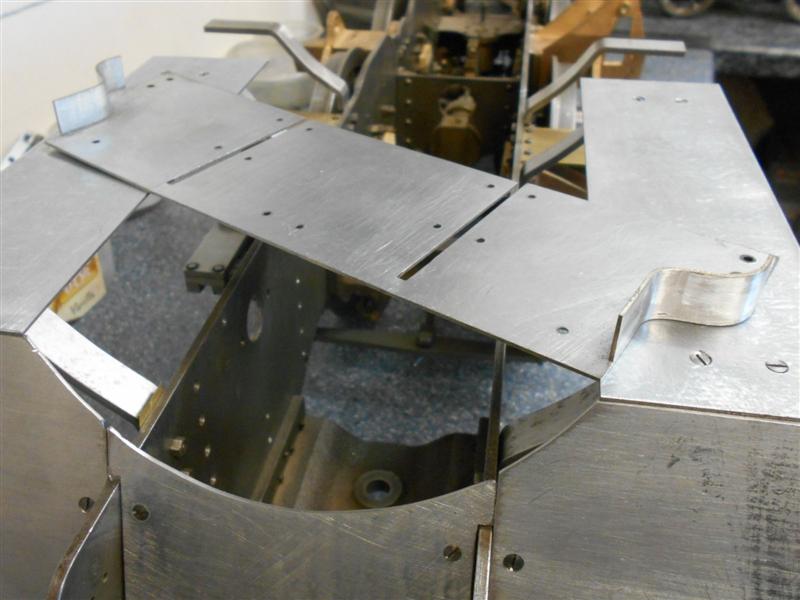
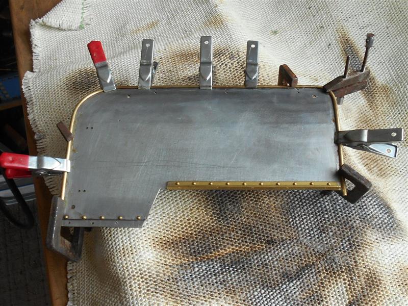
The valance starts as a pelmet at the front of the platform,
becomes like a cornice as it travels up the riser and reverts to being a
pelmet again when it reaches the front footplate section. Marking out this
side panel was achieved by tracing the drawing onto the material and working
by trial and error - do some filing, offer it up, do more filing, offer
it up and so on. Some of the various section are seen to the left. As each
part was made, it was temporarily fixed in place, holes drilled and tapped
etc. and generally tinkered with until it was correct, quite time-consuming
but neccessary. I then made the curved pelmet section for the lower front
section and this has been soldered into place. It's not a good picture,
unfortunately. |
 |
 |
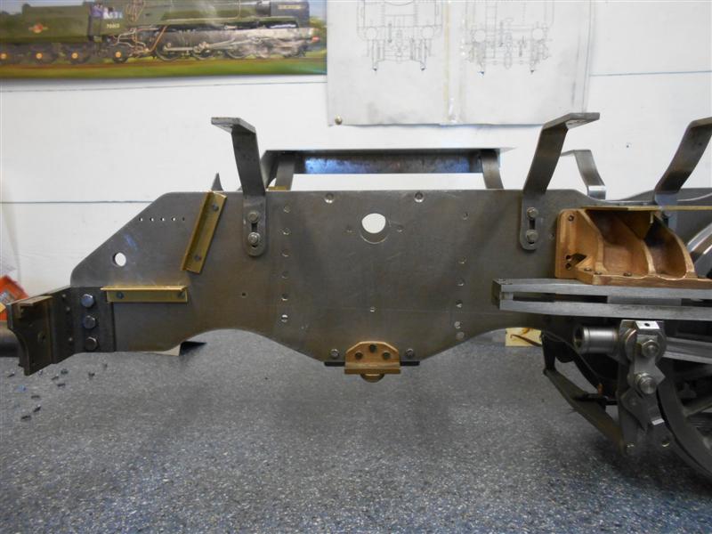
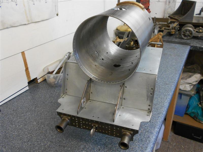
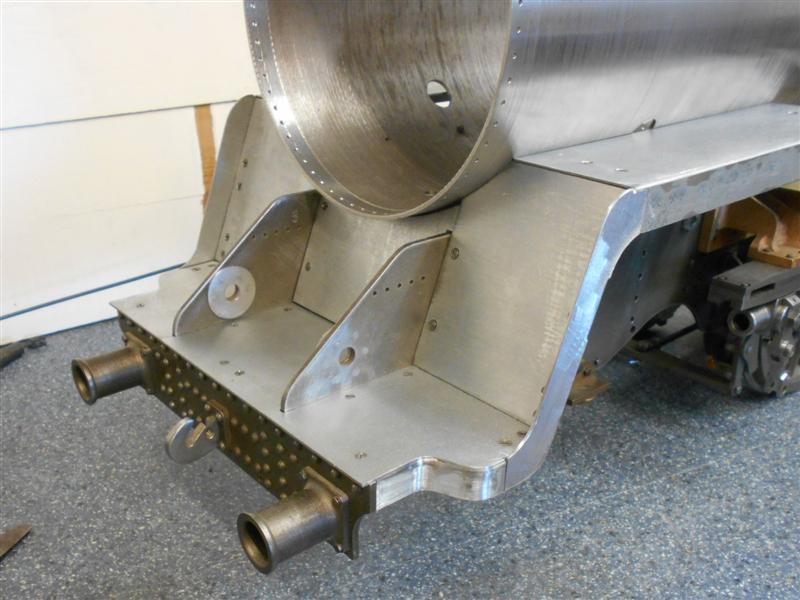
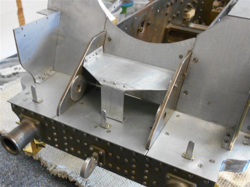
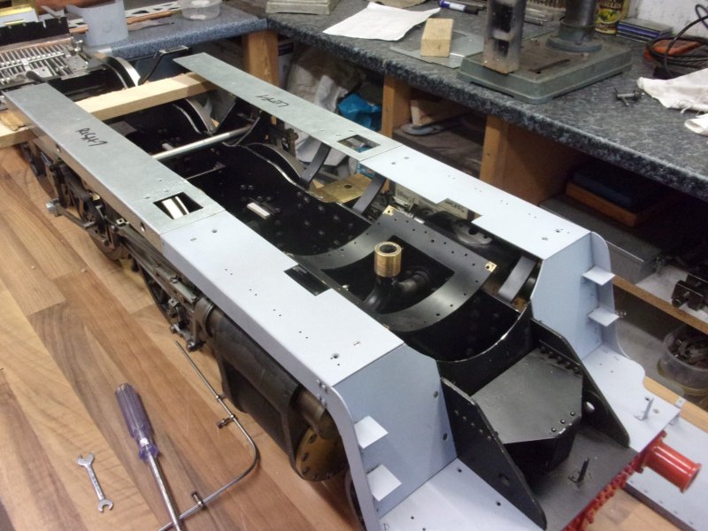
This turned out to be a less-than-smart move because the
front platform cannot now be positioned without removing the buffer beam.
The lifting eye strengtheners on the frames get in the way when trying to
slide the platform in. The answer was to separate the platform into three
sections - they are bolted down separately anyway - but, for now, I have
dropped the buffer beam, fitted the platform and reassembled it all. This
last photo shows the assembly to date. |
 |
| 4. Front Steps |
|
|
 |
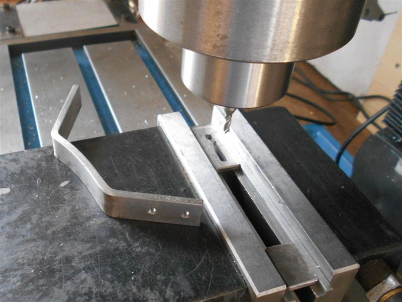
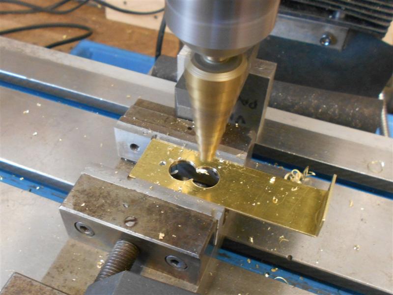
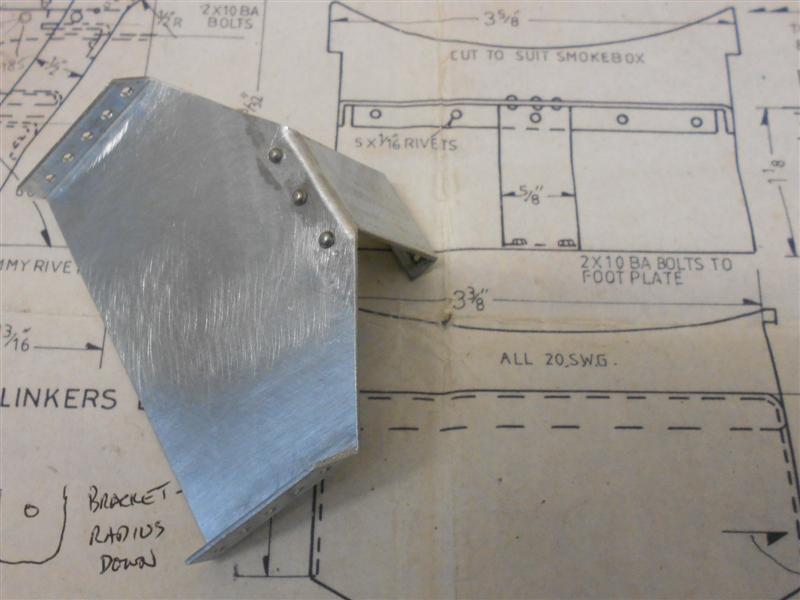
The front steps are now made and there is one tip I would
like to pass on. Don't be frightened to experiment with alternative tools
if the first-choice tool is not available. Here, I needed to create a 7/16"
wide slot but didn't have a slot drill that was suitable. However, the step
drill that I bought from Toolstation (as part of a set of three) is made
from HSS and did the job perfectly. |
 |
 |
The treads were then soldered on and the rear support
bracket made and bolted to the frames. I am going to experiment with a different
way of getting the chequered-plate effect on the steps but more on that
later. I have also made the lower sections of the smoke deflectors, soldered
the footplate steps into position and made the smoke deflector footplate
brackets. |
 |
| 5. Smoke Deflectors |
|
|
 |
The smoke deflector panels were next and all the holes
were drilled on the mill using co-ordinate drilling using the DRO. I have
deviated from drawing and have provided extra holes for the front smokebox
ties and tried to copy the bolting arrangement of the upper and lower sections.
However, the lower bolt holes are where I want them to be, not where they're
supposed to be. and here are the parts all bolted together with the smokebox
temporarily back in place. It takes on a whole new perspective now. |
 |
 |
The next job was soldering the half-round beading on.
Soldering brass to mild steel was something I hadn't done before and my
first efforts were very poor but after some practise I managed to get a
decent bond between the two. I used Fluxite and soft solder, tinning both
parts before clamping together with more flux and gently heating the plate
and adding a little more solder. I've also finished the handrails on the
deflectors and the smokebox door and it completely changes the look of the
loco. |
 |
| 6. Smokebox Platform |
|
|
 |
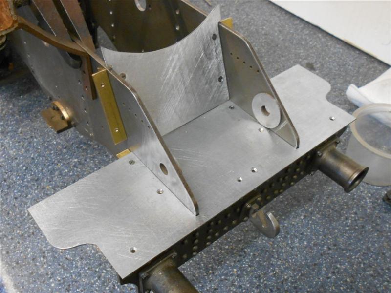
The smokebox platform is drawn with the side
mounting flanges drawn facing downwards but I have made my platform as per
the prototype, facing upwards. The platform was cut out from a single piece
of 20 swg MS plate then bent and drilled. I have dispensed with the rearward
flange and the front support has three dummy rivets. |
 |
| 7. Middle Footplate |
|
|
 |
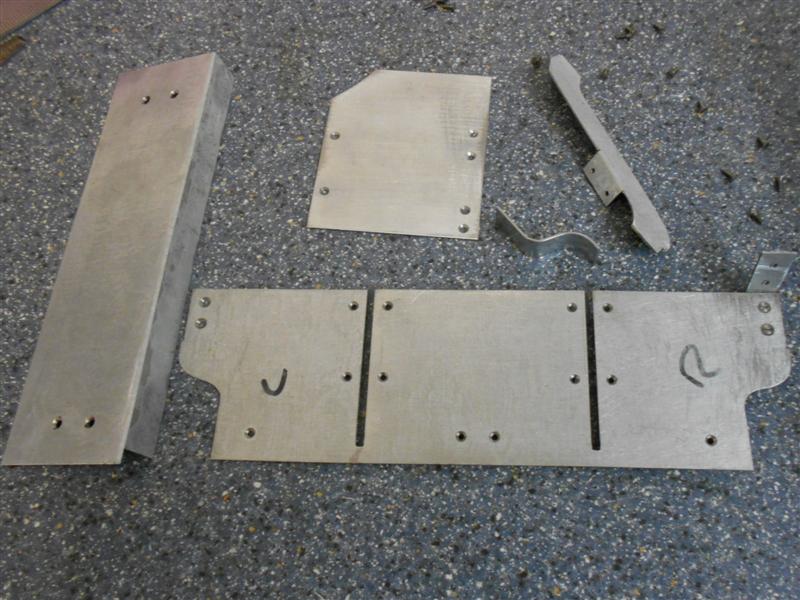
I've cut the middle sections of the footplates from galvanised
steel sheet recovered from a local fabricator's skip. Folding the valances
neatly was a challenge, having only flat steel bars to act as vice-jaw extensions.
Drilling all the holes on the milling machine was straightforward, as was
forming the cutout for the oil pumps. The final job was to mill the valances
to 11/16" and have a straight, true edge. Some of the dimensions need to
be taken with a pinch of salt and I had to remake the oil pump platform
as it was 5/16" too short to allow the priming handle to protrude. The old
ones are to the left in the picture. |
 |
 |
Fixing holes were marked out by eye, then spotted through
to the support brackets, drilled and tapped. I'm using 8BA c/sunk steel
screws for this. The inside edge is just scaled from the drawing at present
but will be trimmed back to suit the boiler cleading when I get to that
job. These will go in the pickle tank for a couple of hours to get the zinc
off, then be rinsed and primed. |
 |
| 8. Sandboxes |
|
|
 |
Rather than make the sand boxes as brass blocks with separate
lids, I have machined the whole thing, except the handles, from solid. They
are dummy boxes anyway so removeable lids are unneccessary. I have used
a handful of the bronze offcuts that were in the scrap box as I can't forsee
another use for these. Allowing 1/32" per side for the lids, I machined
up he six blocks to 9/16" x 7/16" x 13/32" high. Next, the sides were milled
away to leave 1/2" x 3/8" with a 1/8" step for the lid. |
 |
 |
Finally, an 8BA hole was drilled and tapped in each and
1.7mm holes were drilled in the lids for the handles. These were made freehand
with pliers using 1/16" brass around a piece of 1/4" dia steel, then soldered
into place with soft solder. After pickling and priming, they can be bolted
to the footplates. |
| 9. Rear Footplate |
|
|
 |
The driver's side footplate also has the tunnel for the
reversing shaft set into it and, for this, I luckily found an old oval wardrobe
rail of approximately the right size. An angled section of this was cut
from the rail, filed to shape and silver-soldered to the footplate. The
cutaway for the revesing shaft was milled in afterwards using 6mm end mill
to rough out the slot and a 10mm end mill to open it up, stopping short
of the open end. |
 |
 |
There are no real dimensions given so it was a case of
trying to make it look right. I will need to modify one of the dummy sandboxes
to fit into the limited space between the rear of the tunnel and the boiler
cleading. The other side is just straightforward bending and cutting. |
 |
| 10. Brake Pedestal |
|
|
 |
The brake pedestal comprises a collection of parts and
contains the steam brake actuating valve instead of the vacuum brake that
is on the full-size loco. It also doesn't look much like the prototype but
I have made it (mostly) to drawing anyway. The base was made from an offcut
of bronze plate, milling all round to fit the pedestal tube and the various
holes drilled and tapped. The pedestal body was made from 1" square 10 swg
mild steel seam-welded tube and skimmed with a flycutter to reduce the outsides
to 15/16". The top was made from another offcut of the bronze and machined
to finish. I included a locating spigot for the tube and the two parts were
silver-soldered together. The spindle and collar were also made but the
cross-pin drilled and fitted later. |
 |
 |
The fitting on top of the pedestal was turned from 3/4"
brass bar and the internal section trepanned out with a special tool. The
relative depth of the boss was made a few thou less than the height of the
boss on the top of the pedestal. The parting-off was started, then the bar
taken to the mill and set up in the rotary table. Three rows of holes were
drilled using a PCB drill (because these don't need a centre), then returned
to the lathe and finished parting off. I didn't bother to form the raised
section as it is nothing like the prototype anyway. |
 |
 |
The valve disc was turned from 3/4" brass bar, the slot
cut with a slitting saw and the steam passage milled with a 2.5mm slot drill
using the rotary table. The handle was made freehand and a 1/8" square shank
of a tap used to broach the hole. The spindle was offered up to the valve
disc and drilled 1/16", a steel panel pin being used to drive the disc.
The spring is a fairly stong one from the spares box. The final job was
to fix the base with a pair of 6BA screws, care being taken not to break
into the steam port on the rearward side. I still have to fit the drain
pipe but will do this when I do the plumbing,just prior to building up the
cab. I have my doubts that the valve will work without leaking steam all
the time, even though I lapped the two parts together, but I can always
blank it off if that happens. The steam brake is not really an essential
item on the loco. |
 |
| Update 31/01/2021 |
|
|
| I have decided to dispense with the steam
brake and have scrapped all the parts within the pedestal. Instead, I am
using the pedestal to mount the blower valve (where it should be) and have
replumbed the sytem accordingly although I have retained the decorative
elements of the brake at the top of the pedestal. An update on drawing 15
covers the blower parts. |
| 11. Next Item... |
|
|
| |
|
|