| Framework |
| |
1. Base & Platform |
|
 |
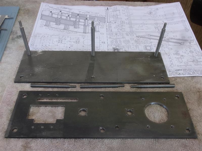
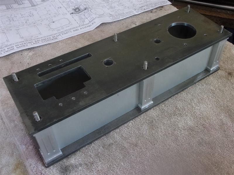
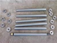
The base and platform have both been made
from 100 x 5 hot-rolled steel and the edges skimmed to clean up. This means
they are 3mm narrower than the drawing shows and the positions of the base
pillars and the columns have been moved inwards by 1.5mm each. Everything
else will go where drawn. The rods through the pillars have been made from
M8 studding and one end turned down and threaded M5 |
|
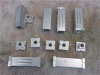
2. Pillars |
|
 |
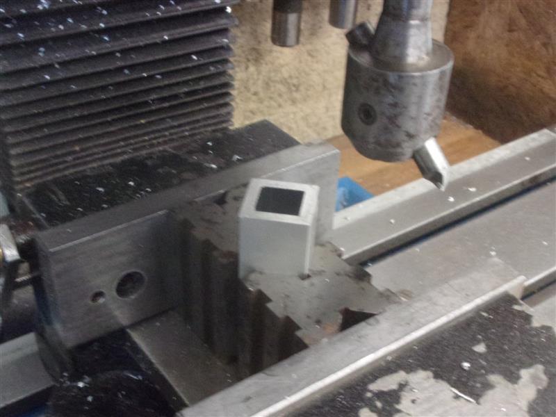
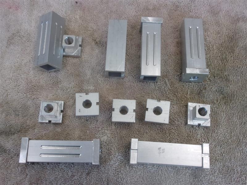
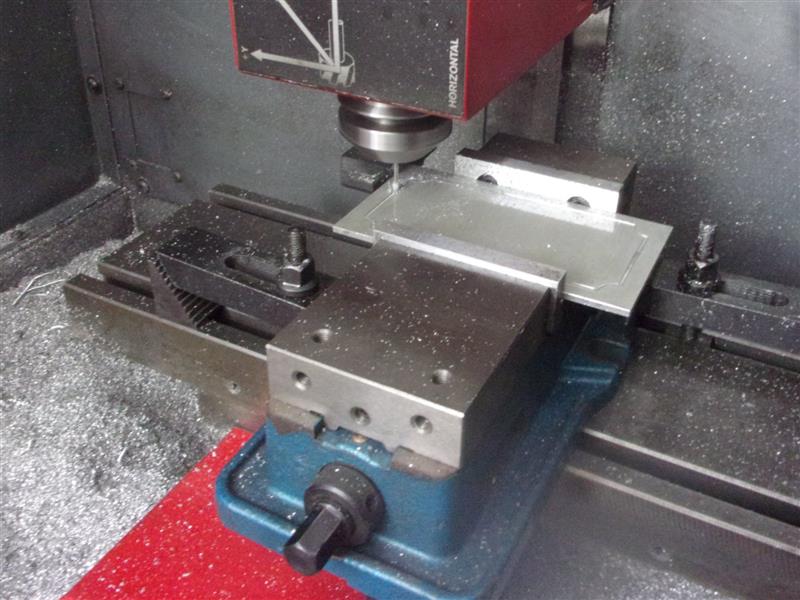
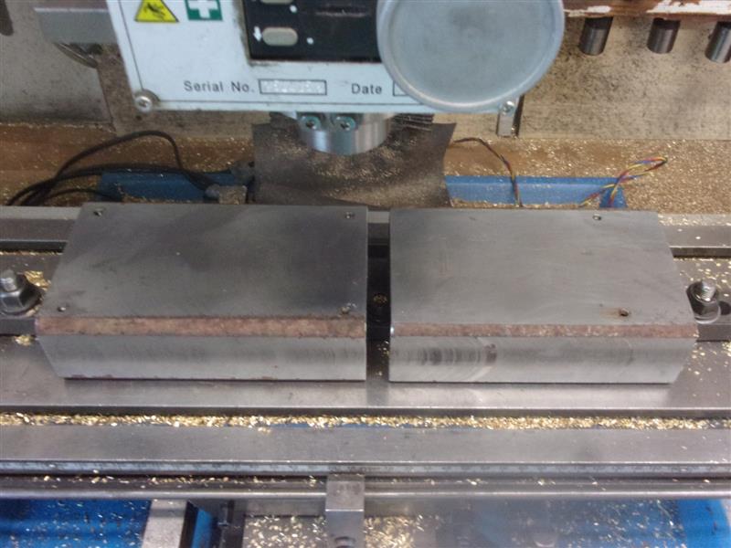
The square pillars that separate the base and the platform
have been made from aluminium box-section with separate aluminium end-caps
for either end. Rather than have my chuck jaws mark the work, I faced the
sawn sections to length with a flycutter in the mill, holding the work between
two vee-blocks to ensure squareness. The end-caps were made from 22mm square
aluminium, milled to fit inside the box-sections and drilled 8.1mm to fit
the studding. The outer faces of the pillars were fluted with a 4mm dia
ball-nosed slot drill, just to add a bit of decoration. The slots in the
end-caps provide support for the face and end panels panels. |
 |
| |
3. Panels |
|
 |
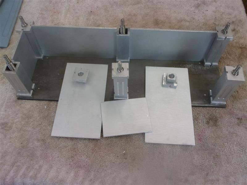
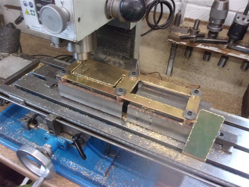
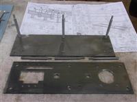
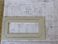
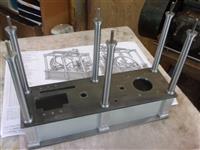
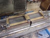
The panels have been cut from 3mm aluminium sheet and
milled to fit exactly between the pillars. The two front panel will have
windows cut through them to allow viewing of the pump, pipework and governor
linkages below the platform. The platform is located on the 8mm studding
and get held in place by the base caps of the columns which are tapped M5.
I took the panels to a friend who has a CNC mill for the next part.
|  |
 |
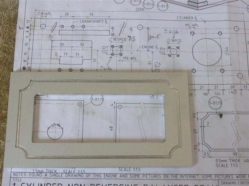
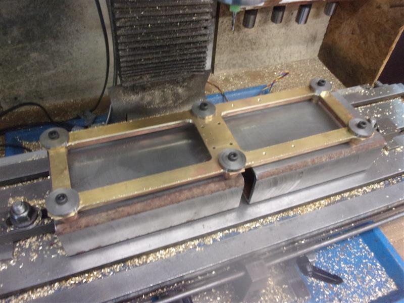
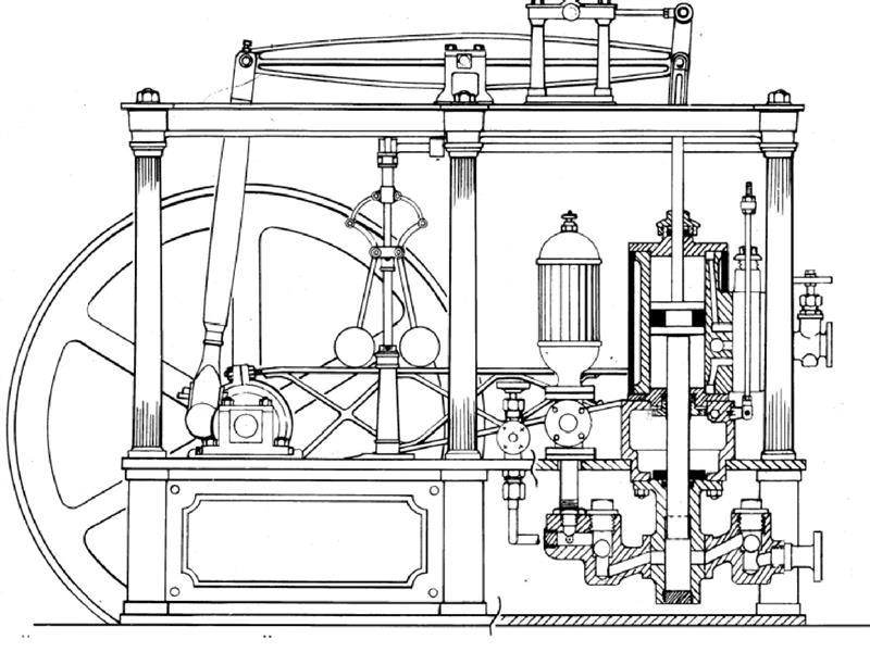
The drawing shows a backing frame and separate panels
which screw to them for access to the underside but I have chosen to make
them as slot-in panels with perspex viewing windows inset into the front
two only. The panels were set against an end stop and the scrollwork cut
in with the 2mm slot drill. It was slow because we only had long-series,
neutral-rake slot drills available and we snapped the first one before getting
half way round the first panel. Then two of the panels had the viewing window
cut out with a decent 4mm slot drill, which sped thing up somewhat.
|  |
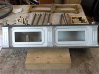 |
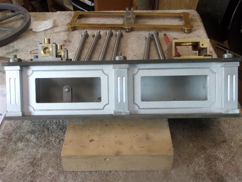
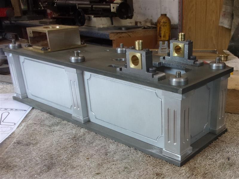
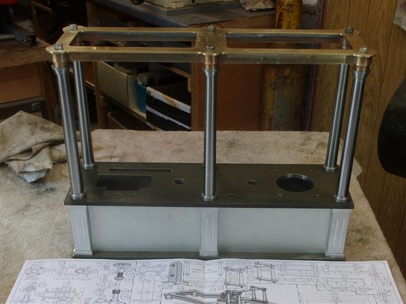
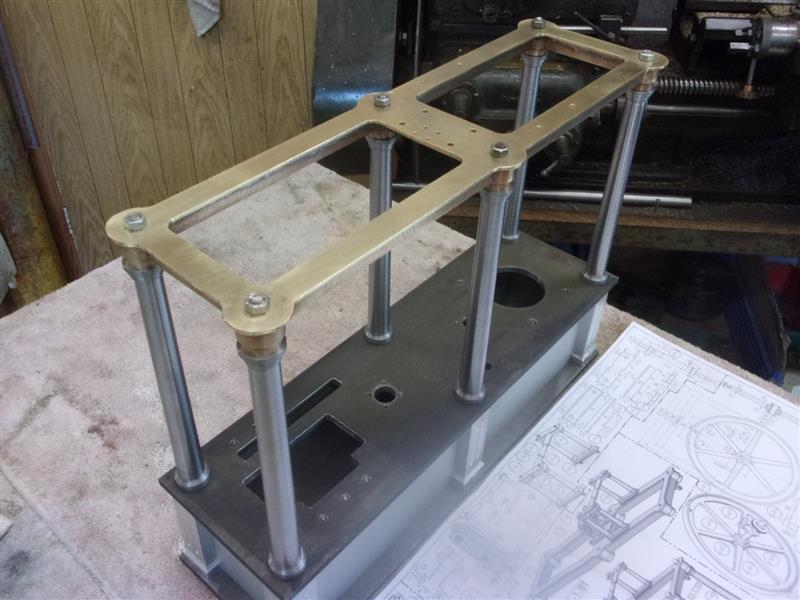
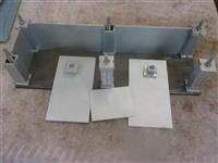
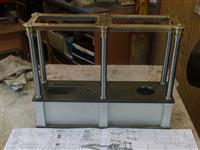
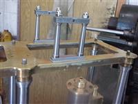
And this is what they look like when assembled. I will
glue the perspex windows to the rear faces at a later time.
|  |
| |
4. Columns |
|
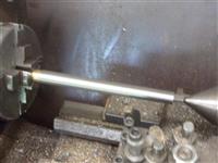 |
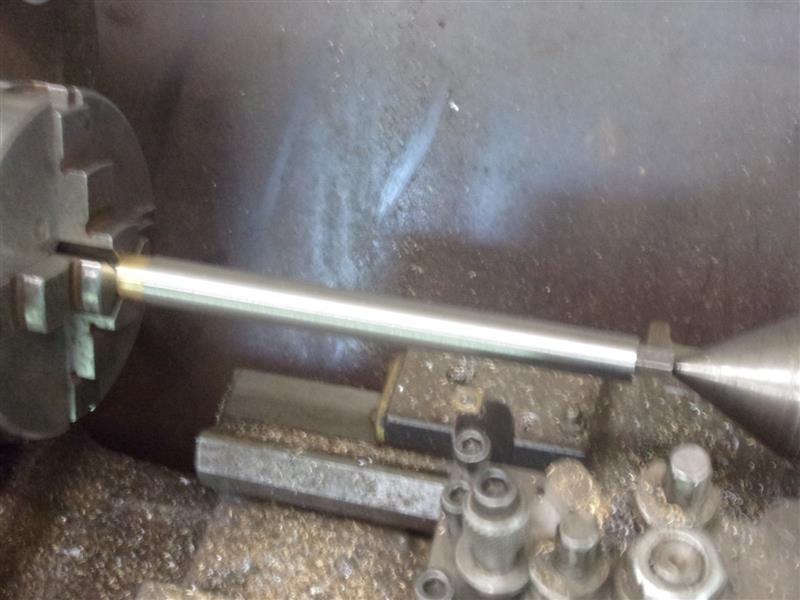
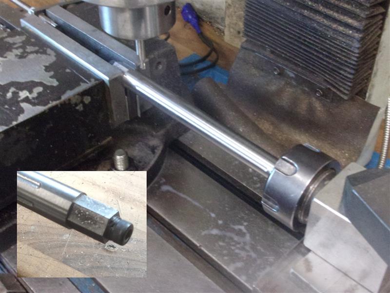
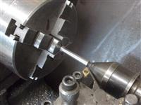
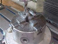
To make the tapered columns, I first cut six lengths of
19mm dia bar, facing them to length, then drilled & tapped each end
M5. A cap screw with spacer was fitted to one end and a centered adaptor
screwd into the other end. The tailstock was offset to the front by 1mm
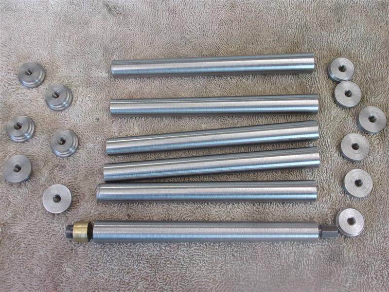
and the diameter turned to size. The top and bottom caps were made from
22mm dia mild steel, also drilling & tapping M5 |
 |
 |
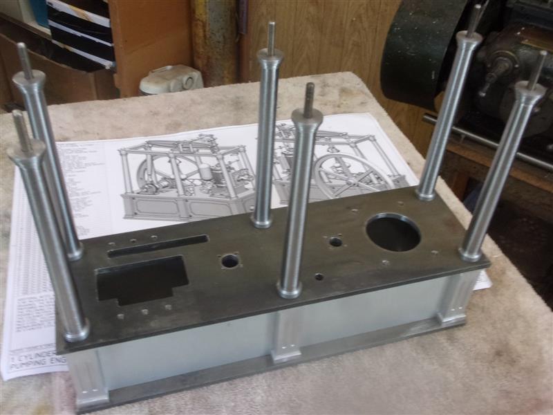
The base caps get screwed down first, followed by the
six pillars. Short lengths of M5 studding are threaded into the tops of
the columns and the top caps screwed down onto them, leaving sufficient
protruding to locate and secure the canopy. Some time later, I removed the
columns and added flutes to them. Indexing was achieved using a hexagon
spacer bolted to the front end. I don't have a tailstock centre for the
mill so used a collet block to support the tail end. |
 |
| |
5. Canopy |
|
 |
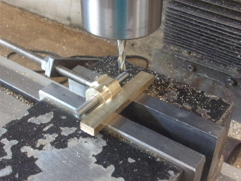
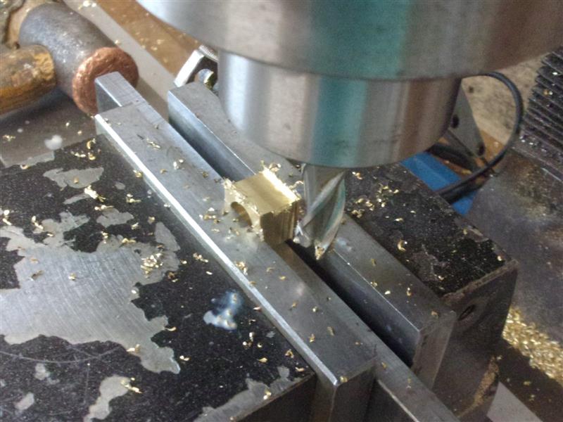
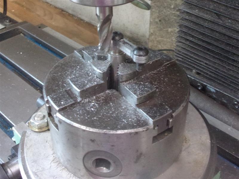
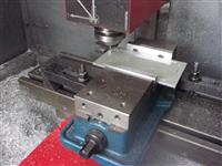
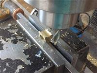
I have fabricated the canopy from a sheet of 16swg brass,
a little thinner than specified on the drawing and made the six corner bosses
from 19mm dia brass. I also made the underside strengtheners from rectangular-section
brass bar milled down to 10mm x 5mm. To help with locating these strengtheners
I milled some 5mm slots in the upper part of the bosses, mounting them on
a 5mm diameter pin. The corners needed two slots at 90° to each other and
this was achieved by rotating with a 5mm packer in the first slot. The two
central bosses required two slots in line, as well as a cross-slot, and
these were bolted together back-to-back and held as shown in the next picture.
The third slot was made as shown earlier. |
 |
 |
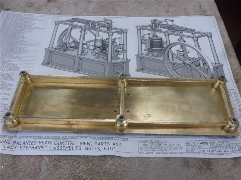
After cleaning up, the parts were assembled with flux
between the components and M5 cap screws to hold it all together. The whole
lot was then soft-soldered together. I didn't fancy hard-soldering this
because of the high risk of distorting the top-plate when the stresses in
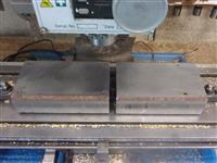
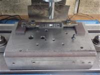
the brass sheet relaxed. I decided to mount the assembly on a fixture and
two of my universal milling aids were brought into use. These are made from
4" x 2" steel box-section, milled all round to be square and the same size.
Holes can be drilled willy-nilley in these for locating, clamping, whatever
I need at the time. Here, I've clamped two in line and drilled and tapped
six holes M5 to match the canopy. |
 |
 |
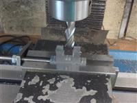
The assembly was bolted down onto the fixture with six
25 mm diameter filing buttons on top to act as milling guides. Various holes
were drilled, as were the corners of the cutouts, then a slot drill used
to clear the middle sections Next, a 12mm dimeter cutter was run round the
outside, using the filing buttons as limiters. |
 |
 |
Because the canopy is symmetrical, I was able to turn
it over and bolt it down again to do the holes on the underside, all still
using the DRO for accurate placement, albeit mirror-image to the drawing.
The corners and central bosses were shaped by filing and with sanding drums
in the Dremel and a test fit of the canopy undertaken. |
 |
| |
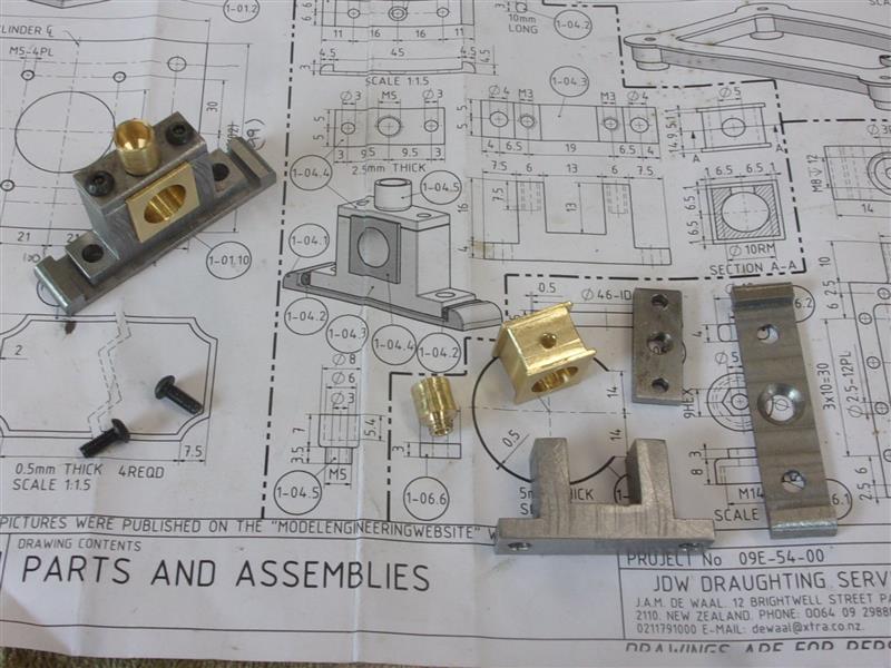
6. Crankshaft Bearings |
|
 |
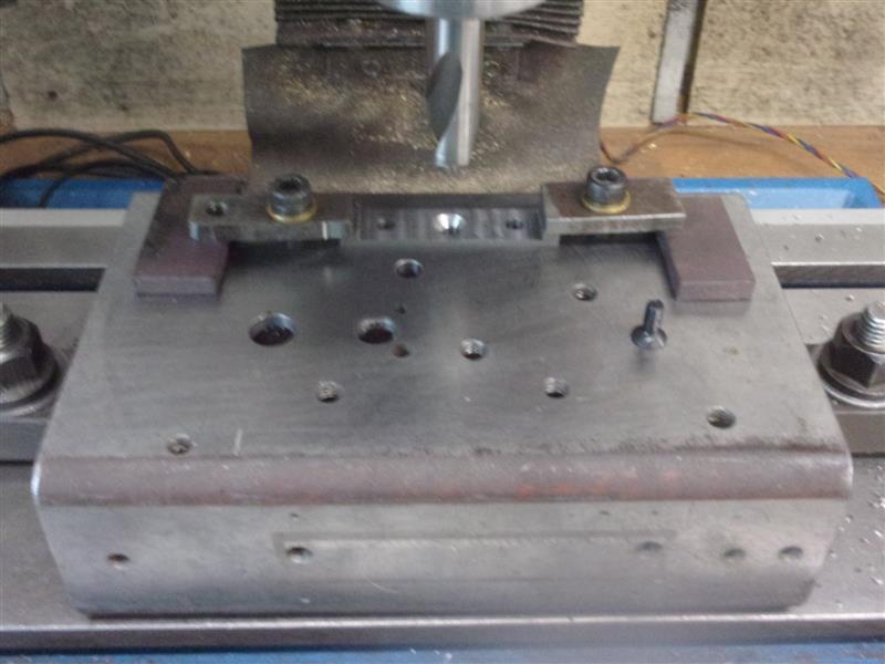
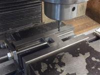
There are a few different parts that make each
of the crankshaft bearings but the two assemblies are identical. The first parts
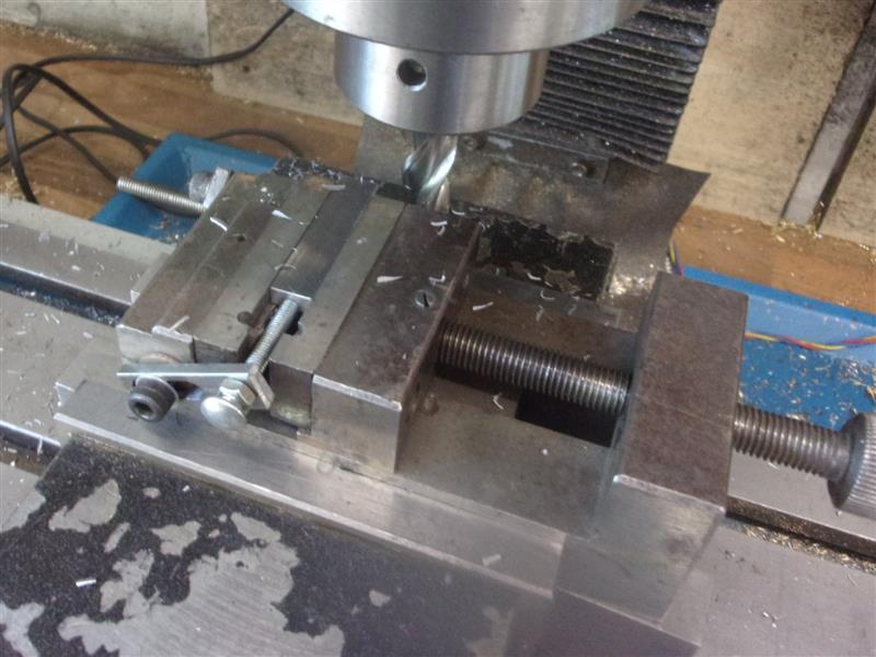
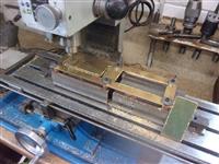
I made were the crankshaft bearing block bases, cut from some 1/2" x 3/16" ground flat stock.
The centre section needed to be reduced to 1.5mm thick and one of my mill fixtures
came into play again. After milling, three 4.1 diameter holes were drilled and the centre one countersunk to accept an M4 screw to just below the surface. |
 |
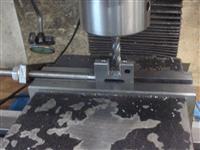
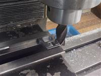
Next I made the bearing blocks from some 30 x 12 black
bar, a bit large but giving me a substantial section to hold in the vice.
After skimming them to 10mm thick, the sides and centre were roughed out
with a 10mm slot drill then finished to size with a 12mm one. All holes
were drilled and tapped in the same setup. Then they were flipped over,
the base milled to finished size and the end trimmed to length, too. The
two bearings were made from some bronze offcuts. Milled all round first,
drilled, bored and reamed 10mm on the lathe using a s/c 4-jaw chuck, them
back to the mill to put the 10mm slots in all round. |
 |
 |
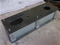
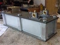
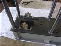
Two top plates were made along with a couple of simple
oil cups. These are all the parts that go to make the bearing assembly except
for a pair of oval wedges that fit each end of the bearing blocks and seem
a bit of a nonsense to me. And this is how they are mounted on the platform.
Different fasteners will be used at final assembly depending on what looks
most authentic. |
 |
| |
7. Watt's Linkage Support |
|
 |
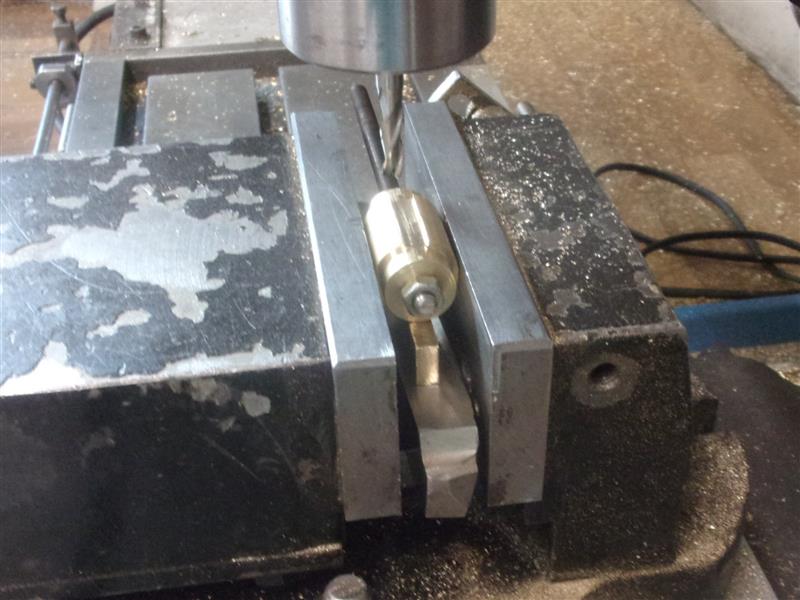
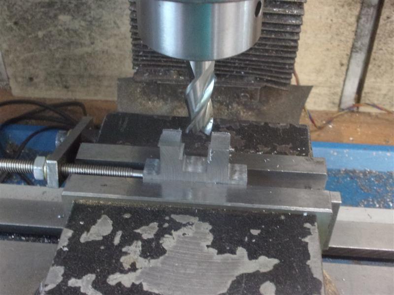
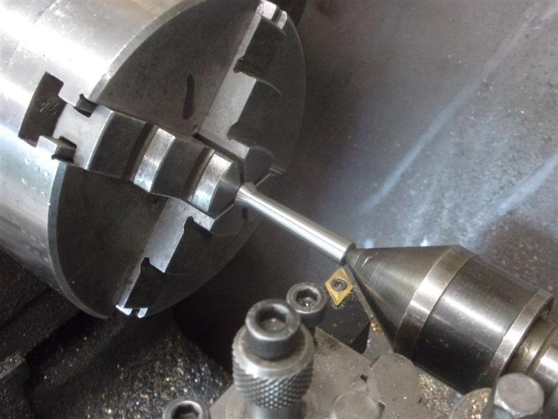
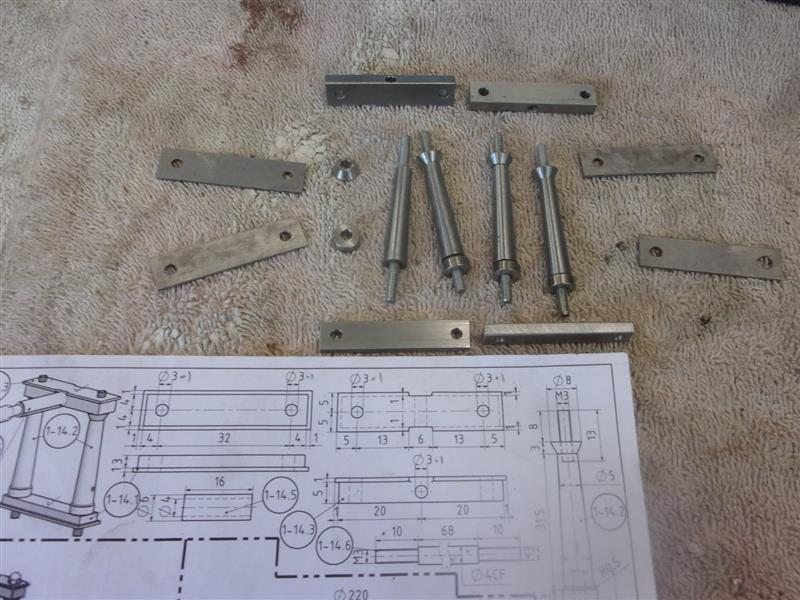
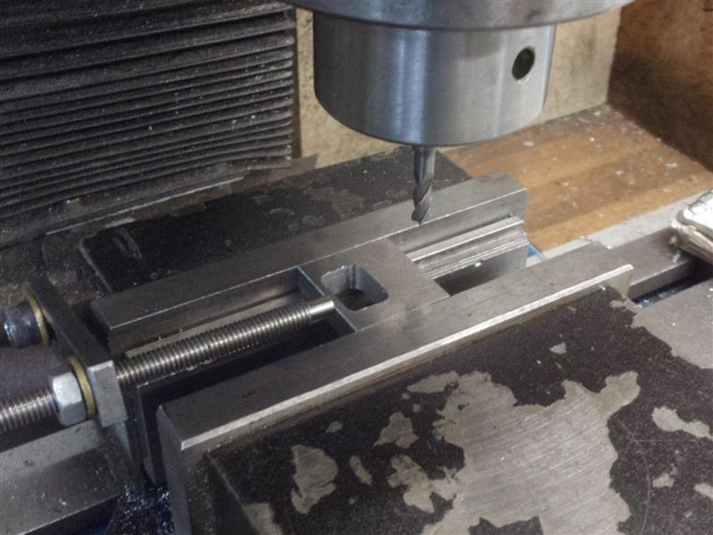
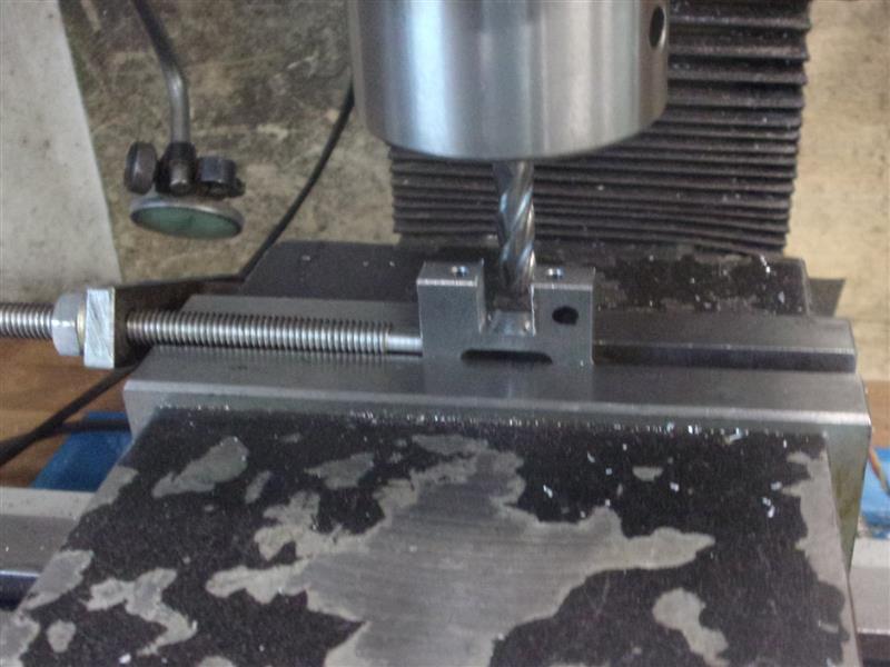
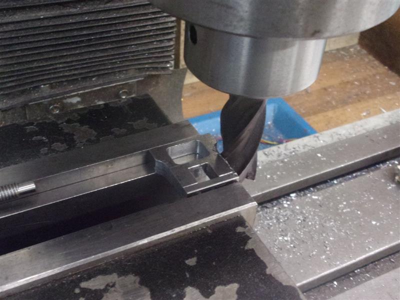
As with the main pillars, I opted to make these smaller
pillars and bases as separate components and then screw them together. For
the tapered section, I parted them off to length, drilled & tapped each
end M3 but with a decent centre at one end, then turned them using the compound
slide. Four pieces of 1.2mm steel made the top and bottom plates while some
3/8" x 1/8" and 3/8" x 3/16" covered the other sections, being faced to
length the easy way here. |
 |
 |
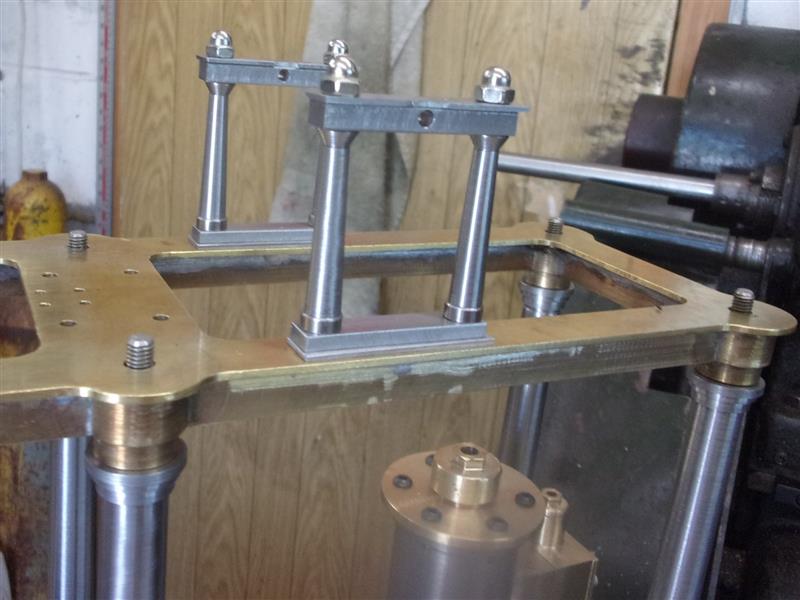
This is the collection of small parts that complete the
assembly and here they are on top of the canopy. Some M3 dome nuts pretty
things up a bit. |
 |
| |
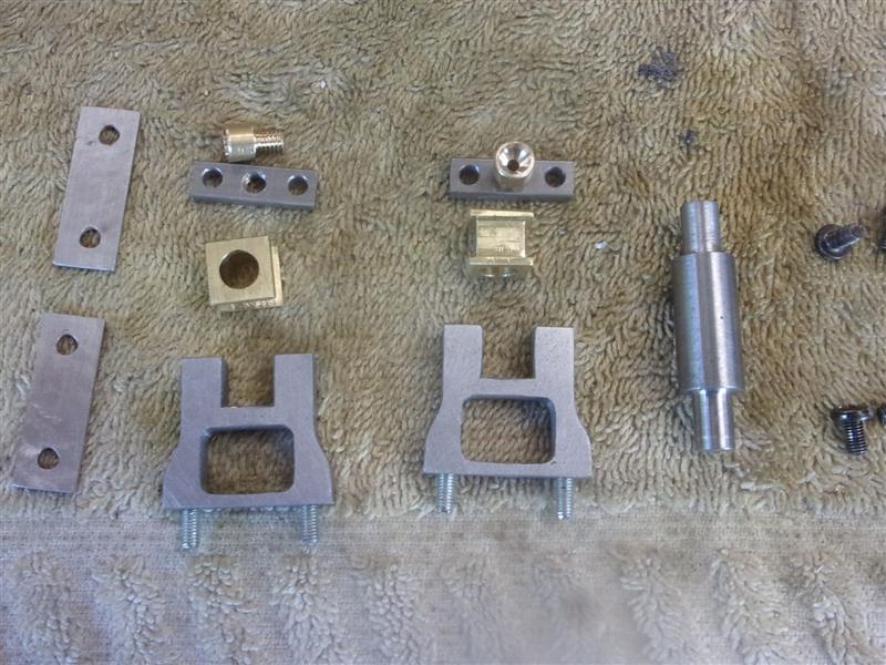
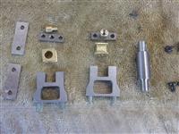
8. Beam Supports |
|
 |
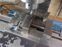
I made the main section of the two beam supports from
some 1" x 1/4" bright flat steel but haven't bothered to reduce the thickness
to the specified 6mm, just rubbing up the outsides for a better finish.
After squaring off and finishing to length, I used a 4mm end mill to clear
away the lower section of each upstand in turn. They were then stood on
end and the two upper and two lower mounting holes drilled 2.5mm diameter
for M3 and the bearing housing machined with a 6mm end mill. |
 |
 |
The bearing retaining plates were made from 1/4" x 1/8"
mild steel stock, drilling the three holes and hacksawing the two parts
from the bar. Then they were screwed to the upstands, mounted in the vice
and the sides milled away with a 16mm end mill. This ensures the parts stay
in line. The bearing blocks were made from some bronze offcuts in a similar
manner to the crankshaft bearings covered earlier. The pivot pin was also
made, a simple bar turned from 7/16" diameter stock bar and a couple of
simple oil cups from some 1/4" dia brass |
 |
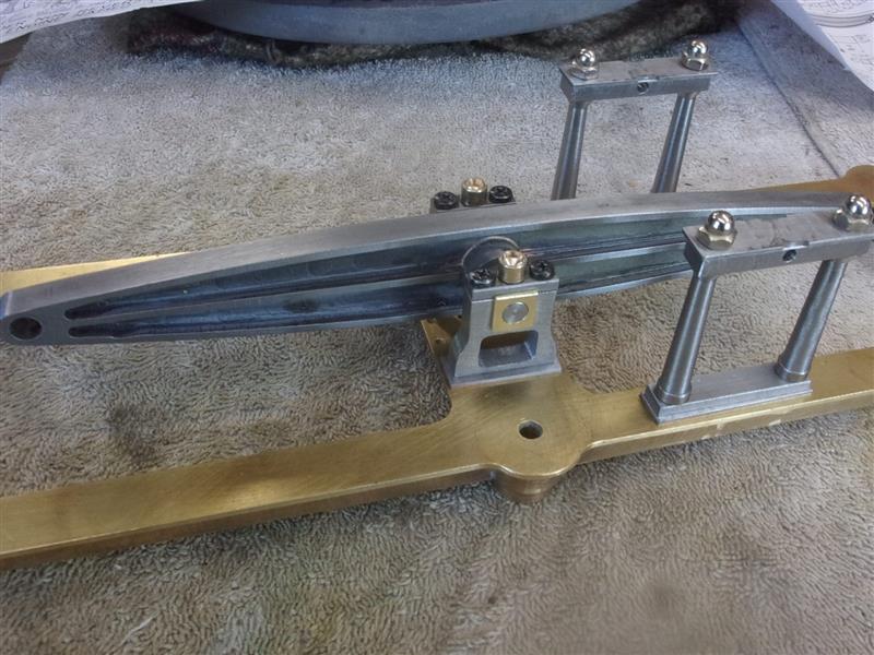
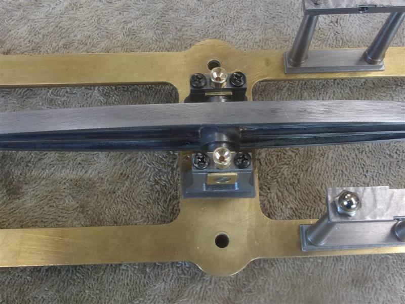
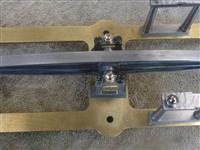
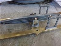 |
Finally the parts, along with the beam, were assembled
in postion on the canopy. |
 |
| |
9. Watts Linkage Assembly |
|
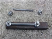 |
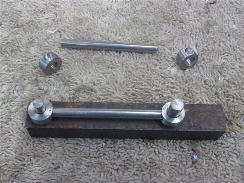
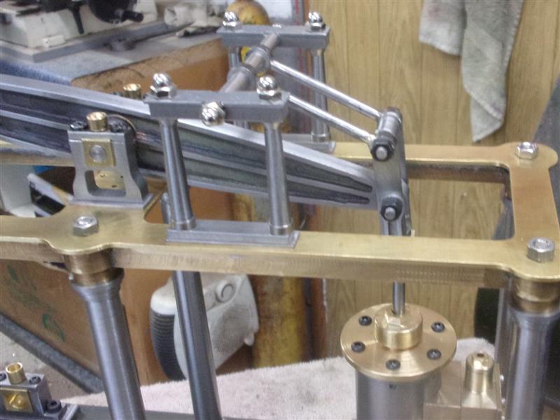
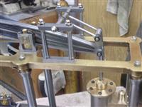
I've now completed the various components of the Watt's
Linkage system and most of it is simple fabrication. I have made the lifting
arms different to that depicted on the drawing, making a fixture to locate
the components and silver-soldering them together. This keeps the spacing
accurate. The fancy-looking arms on the lower section of the Watt's linkage
were drilled and reamed 5mm diameter, then mounted onto a mandrel on the
rotary table using button-head screws, which have the correct outside diameter,
to hold them down and the outside profile machined. |
 |
 |
The other bits and pieces don't warrant a write-up but
here are a couple of pictures of the various parts assembled. One in the
upper position and one in the lower position. |
 |
| |
10. Next Item |
|
 |
|
|