| Cylinder & Governor |
| |
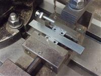
1. Cylinder Mounting Frame |
|
 |
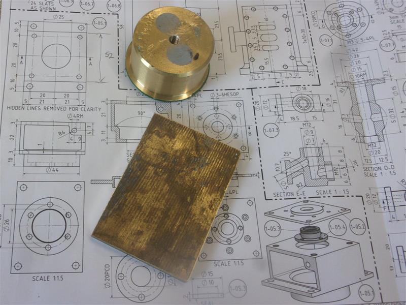
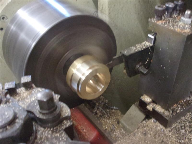
This part I have fabricated from various sections of brass
bar. The first part made was the bottom of the assembly, a cylindrical section
that locates in the platform. The base ring was machined first, drilled
and bored through, a locating spigot turned on the front, then parted off. |
 |
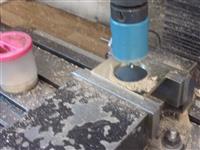 |
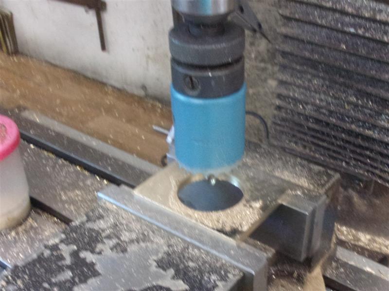
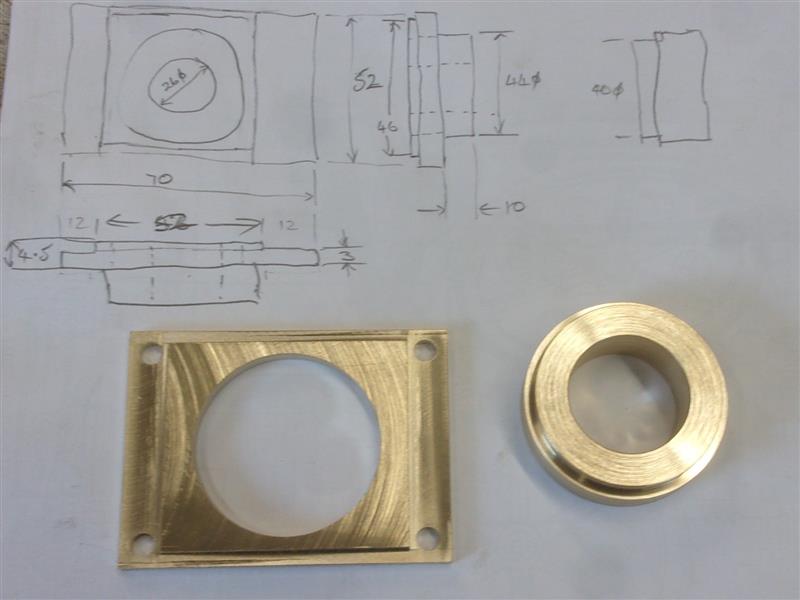
The base plate was milled all roumd to size, then the
centre removed with a 38mm hole saw before finishing with the boring head.
The upper face of the base plate was thinned to leave locating faces for
the two side pieces. |
 |
 |
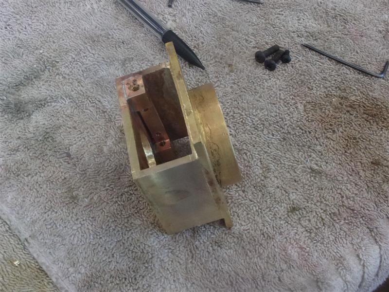
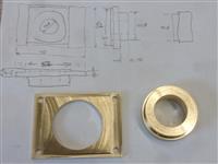
Hard-soldered together with 55% silver solder. After cleaning
up, the base was returned to the lathe and the inside of the boss bored
out to size. Then the two sides and top piece were silver-soldered into
place. Easy to say but much juggling with clamps to get it all to hold together. |
 |
 |
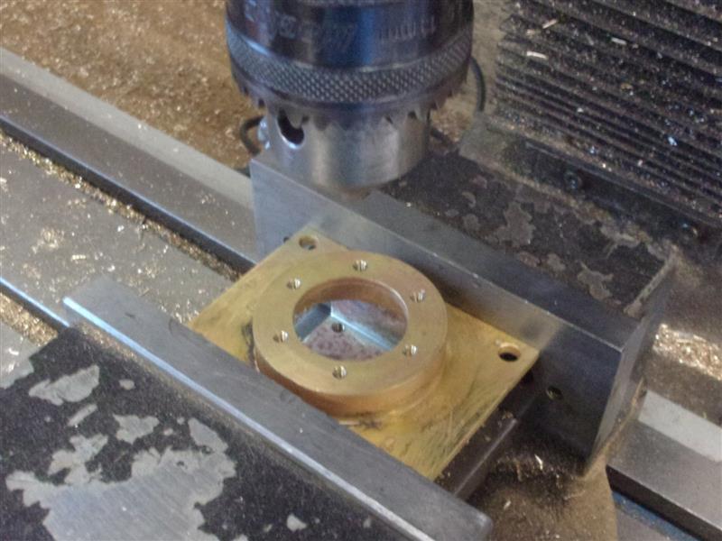
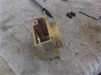
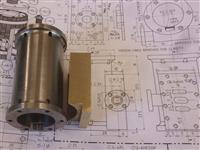
The rest of the holes were drilled and tapped to suit.
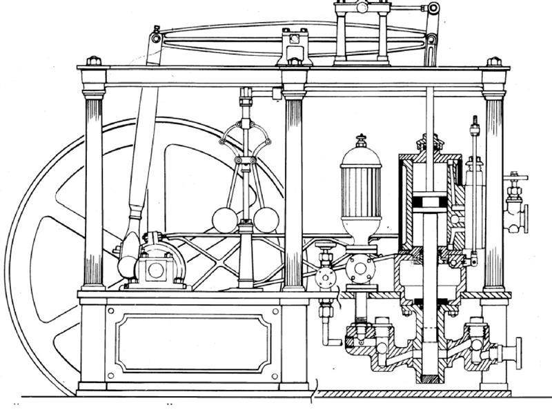
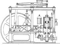
The drawing shows a full-length cast-in section which carries the pivot
rod for the lower valve link rods but I have fabricated something a little
different and soft-soldered it into place but with a pair of M3 screws for
additional support. |
 |
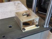 |
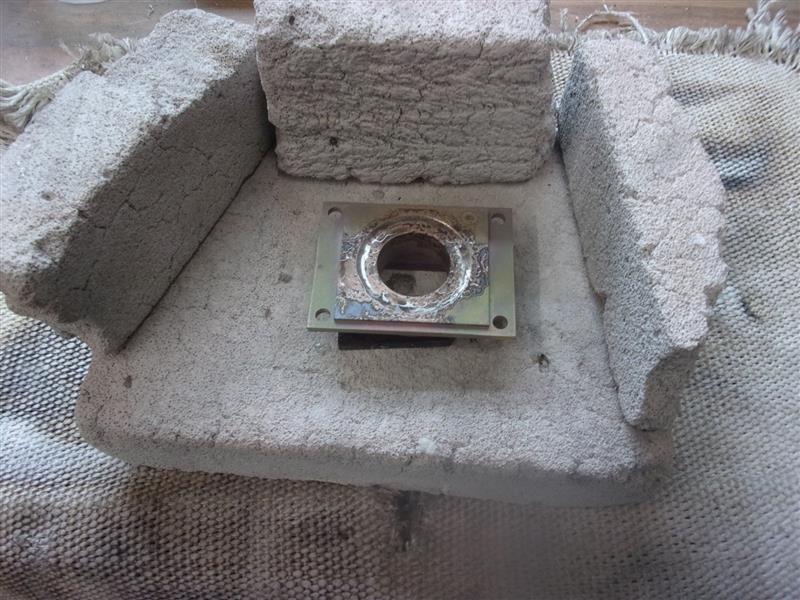
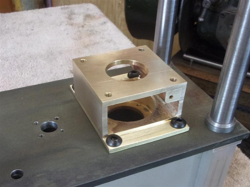
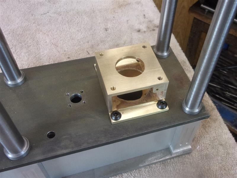
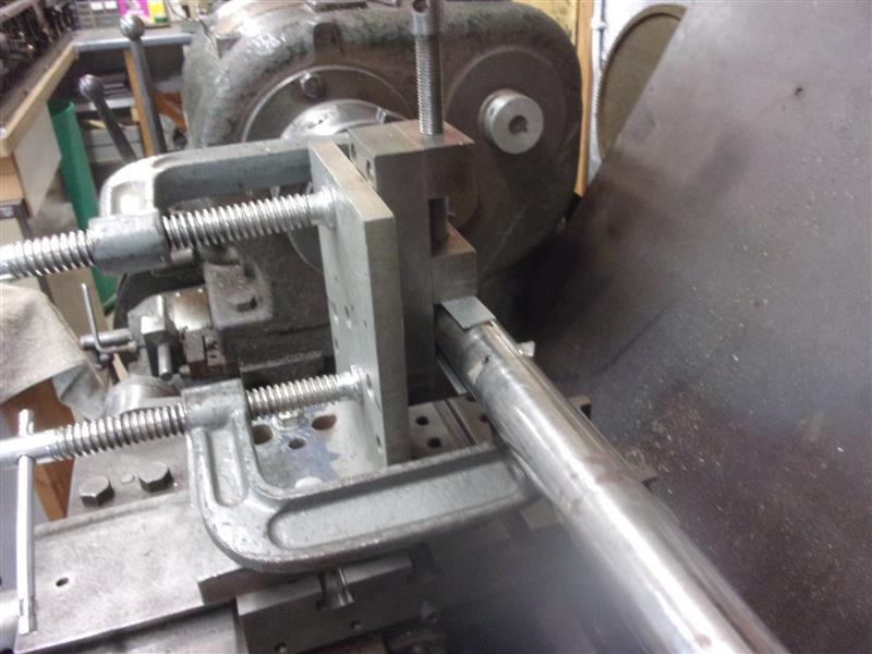
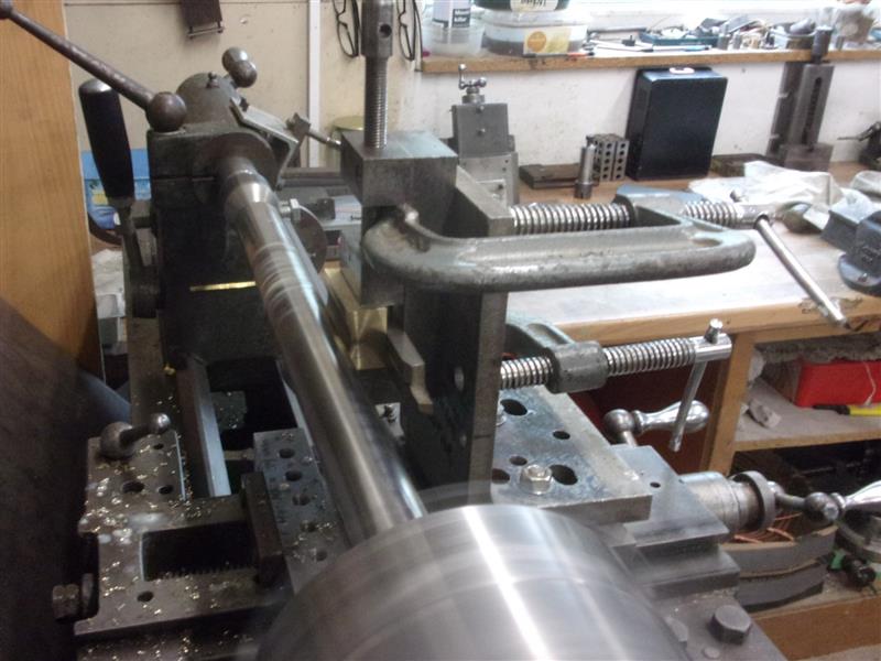
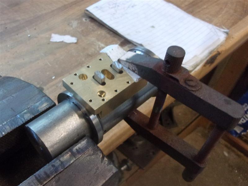
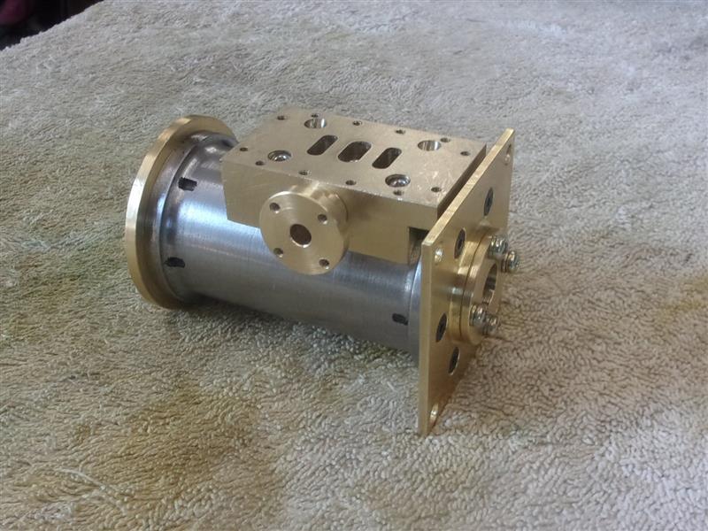
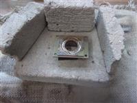
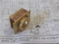
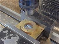
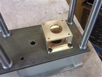
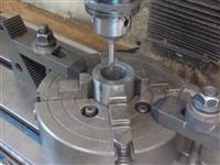
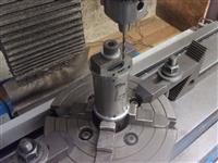
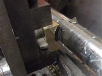
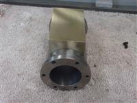
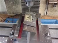
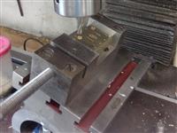
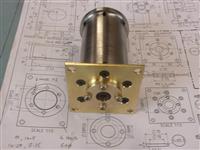
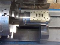
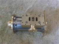
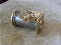
And, finally, a couple of pictures of it mounted in place
on the platform. |
 |
| |
2. Cylinder |
|
 |
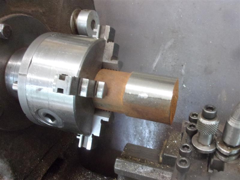
I found a lump of cast iron in the scrap box so decided
to make the cylinder from that. Wish I hadn't, tough as old boots but should
be OK. After roughing out, I finished the billet to length, then drilled
and bored to just below 25mm diameter. I was planning on using a between-centres
boring bar to get to finished size but the parallelism was so good, I just
finished to size instead. Obviously. it will be honed later. Before finishing
the outside, I moved over to the mill and drilled and tapped the holes for
the two end caps, centering off the bore and using the DRO to position the
holes. The holes break out at the back of the flanges so better to do now
and save on broken drills. |
 |
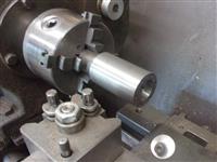 |
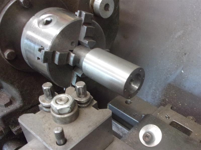
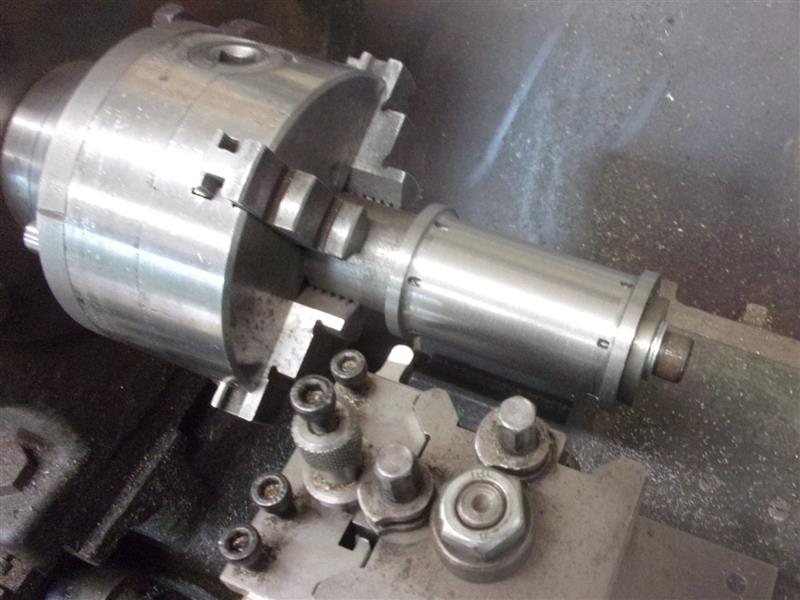
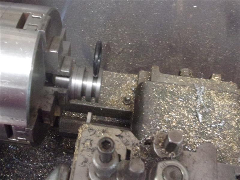
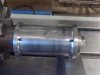
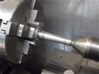
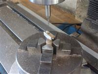
Back on the lathe, a mandrel was machined from some 1.1/4"
diameter stock, turned 25mm diameter and tapped M8, the work being clamped
on with a 6mm thick end cap and Allen bolt.Then the outer form was machined
using a freehand-ground 6mm radius tool. Julius shows the cylinder undercut
to 34mm diameter but I have left mine at 35mm to thicken the wall - less
chance of the steam ports breaking out if the small drill wanders off-line
a little. |
 |
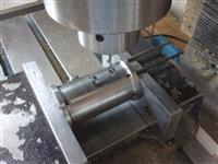 |
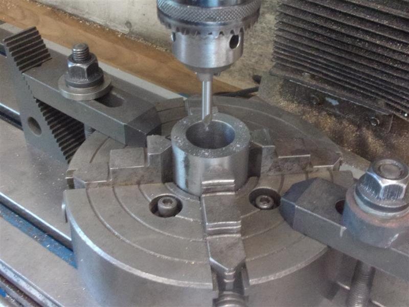
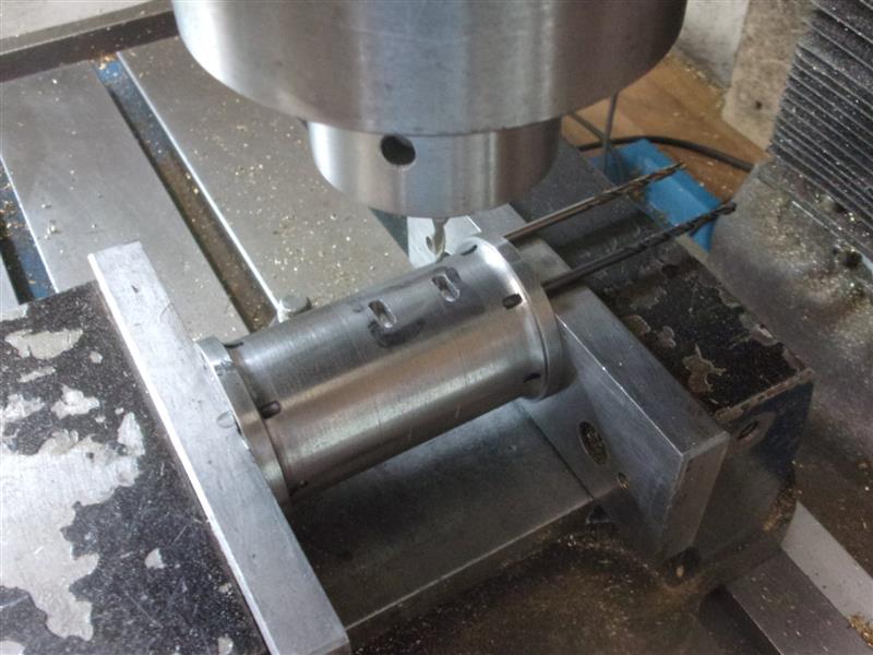
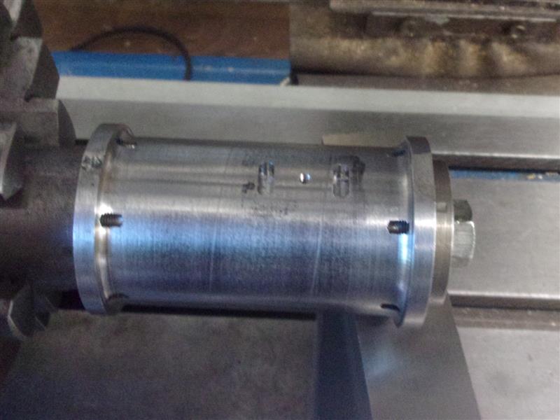
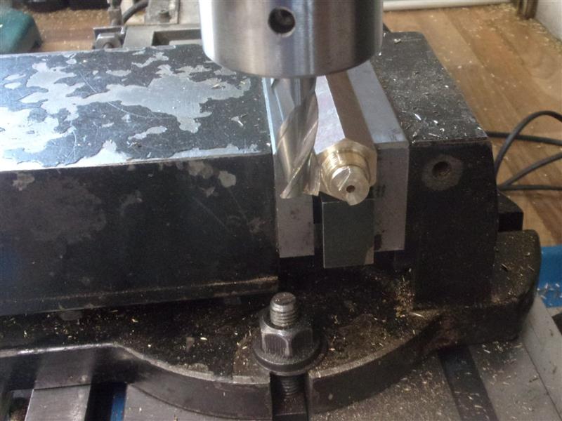
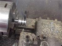
I thought I would put the steam ports in before making
the steam chest and used a pair of drills in the end-cap holes to get the
cylinder correctly aligned. The wall thickness is 5mm so I drilled three
holes 2.5mm diameter x 4mm deep for each port, then opened them up with
a 3mm slot drill, again being very careful not to go below 4mm deep. I set
the mandrel up on the mill table so that I could drill the steam passages,
here just clocking it out the easy way. |
 |
 |
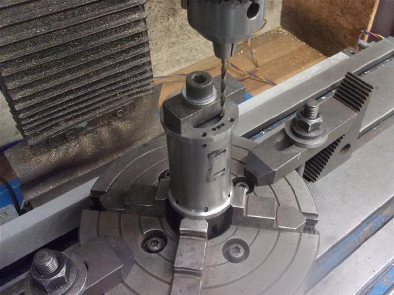
Then I centre-drilled and drilled three 2.4mm diameter
holes from each end until they met the ports. Because the ports are offset,
the longer side was just beyond the flute-length of the drill so very small
pecks were taken near the ends. The ends were also recessed by 4mm to clear
the end caps using a 4mm slot drill. |
|
| |
3. Steam Chest Base |
|
 |
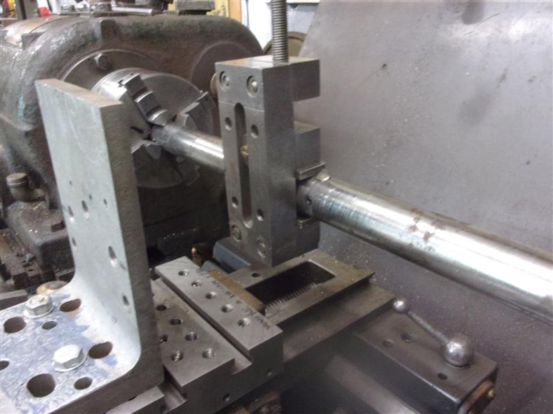
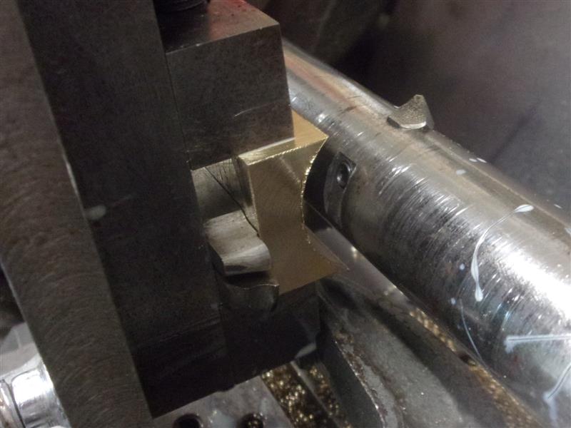
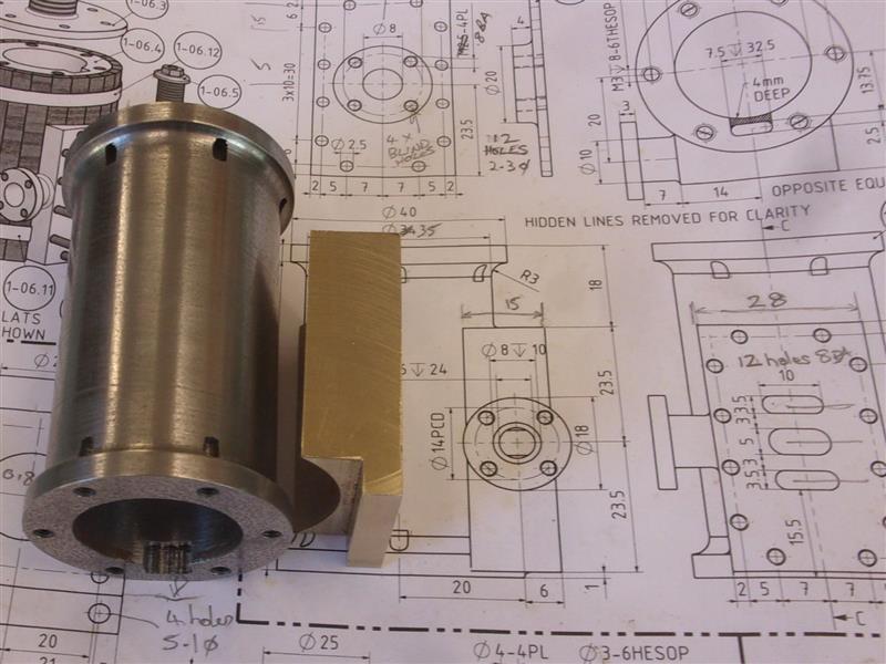
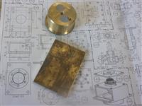
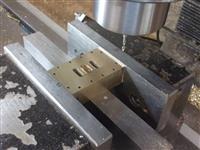
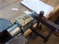
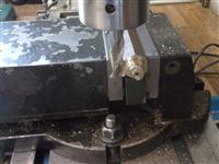
I started making this by milling up a block of bronze
to 47mm x 28mm x 15mm and then needed to form the underside shape to fit
the cylinder. I found this easiest to do on the lathe and swapped over my
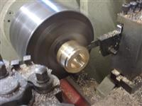
cross-slides to allow mounting of an angle plate. I am lucky because this
takes just a few minutes because of how the lathe is constructed. I already
have a between-centres boring bar suitable for the job and this was set
to 35mm diameter and loaded to the lathe. A small vice was then nipped onto
the bar with packing pieces to set the height correctly and an angle plate
loosely clamped to the cross-slide. |
 |
 |
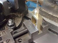
The vice was then clamped to the angle plate and the angle
plate tightened down. A bit Heath-Robinson but accurate enough and strong
enough to do the job. The workpiece was loaded to the vice and cuts taken
until the thinnest part measured 8mm. |
 |
 |
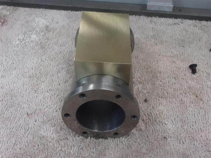
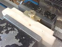
Test-fitted to the cylinder and all appears fine. The
underside of one end was milled away to clear the cylinder flange. It would
look better if it were shaped to fit properly but it will be hidden beneath
the cylinder cladding so I decided not to bother. |
 |
 |
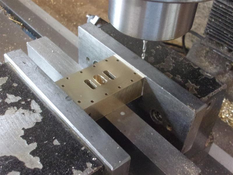
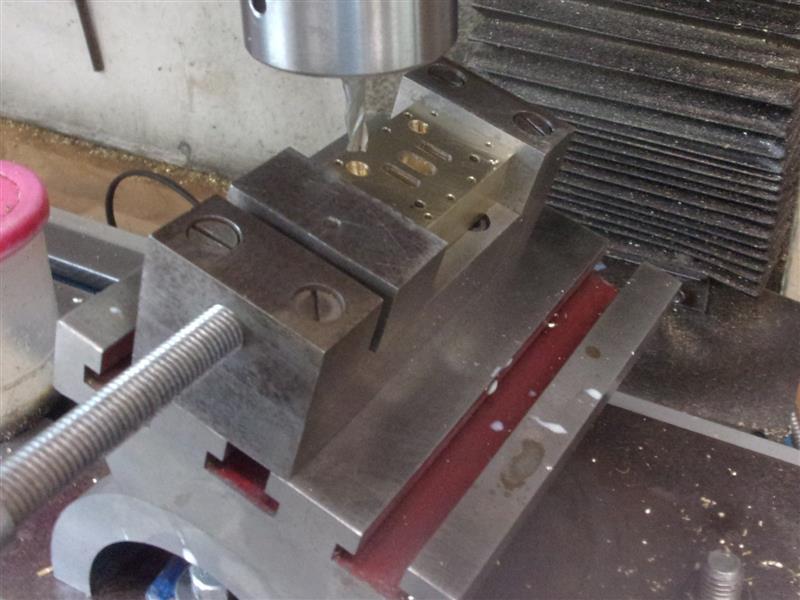
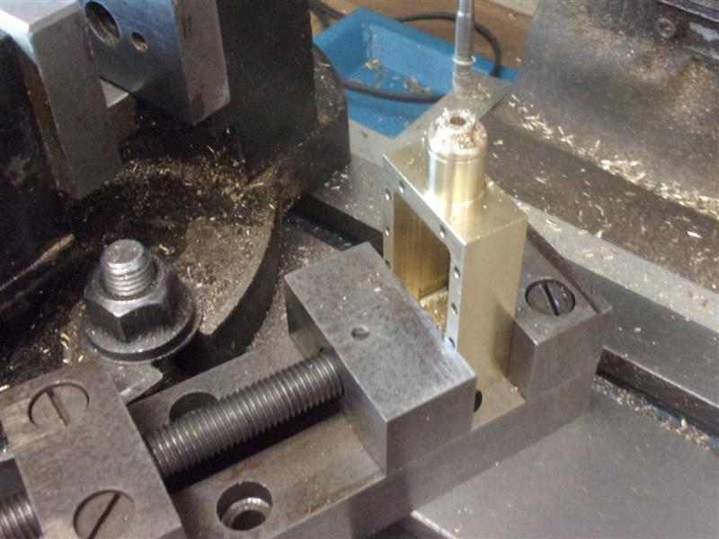
The steam ports were milled out next, the two inlet ports
going all the way through and the exhaust port for a depth of 6mm, leaving
a 2mm wall at the bottom of the port. A 2.6mm hole was then drilled through
the exhaust port to provide the first fixing point. After that, twelve holes
were drilled and tapped to take the fixing bolts. The top was then lapped
on some fine emery cloth on a surface table to remove the burrs but keep
the nice, crisp edges of the ports. |
 |
 |
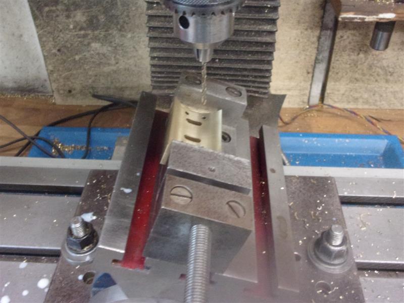
With the ports visible on the underside, I was able to
mark where I wanted four clamping screws to go but I want them square to
the cylinder, not the top of the steam chest base. Also, the holes should
miss the steam passages if I'm careful. I set my tilt-plate visually and
four holes were drilled through at 2.6mm diameter. Then the workpiece was
flipped over and a 3/16" diameter slot drill used to counterbore the four
holes to take the heads of 2.5mm cap screws. |
 |
| |
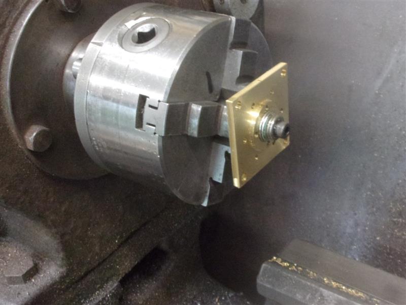
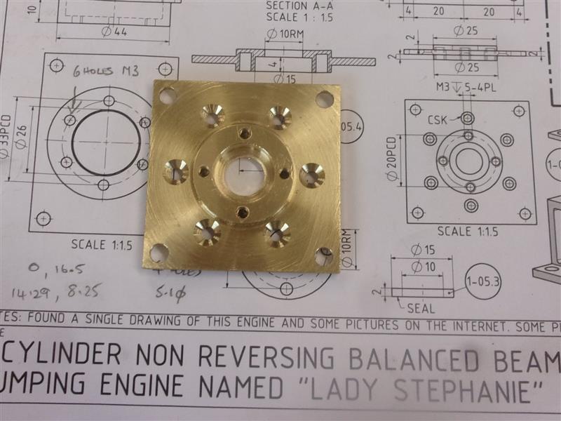
4. Cylinder Bottom Cap |
|
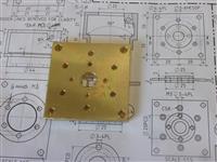 |
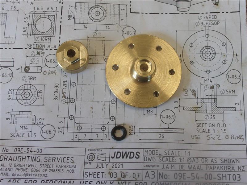
I have some plates that I thought were brass but it turns
out they are a bronze of some sort, a bit chewy like phosphor bronze but
light yellow in colour. 'Twill suffice. After cleaning up all round to 48
x 48 x 6, I then set up to drill all the holes including reaming the 10mm
diameter centre hole. I nearly messed up though, just remembering in time
that the four inner holes are blind, tapped M3 x 4 deep. I turned up a 10mm
mandrel in the lathe and used this to machine the spigots on either side
to ensure concentricity. |
 |
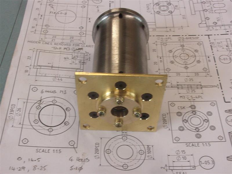
 |
The spigot for the cylinder was made bang-on size but
the platform one was made a few thou sloppy. Then it was held in a normal
chuck and the "O" ring recess bored out. I also made the cap but adapted
it so that it closes fully on the "O" ring; the drawing dimensions leave
it protruding by 2mm. And, finally, fitted to the base of the cylinder with
M3 countersunk screws complete with end cap and "O" ring in place |
 |
| |
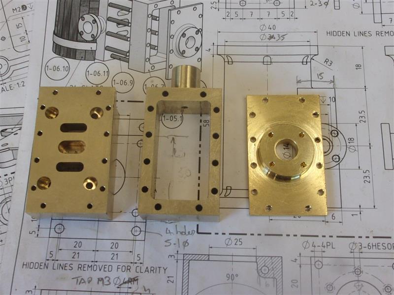
5. Cylinder Assembly |
|
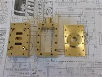 |
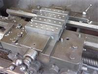
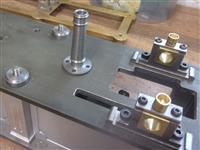
So these are the three main parts of the steam chest assembly.
I made some wedges to locate the steam chest base accurately to the cylinder
body, using the mandrel as a third hand, and clamped the two together, being
very careful not to damage the top face. |
 |
 |
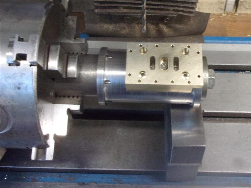
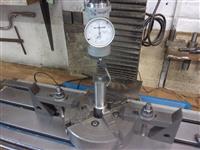
I set the mandrel up on my rotary table, clocked out the
centreline and loaded the workpiece. After lining everything up the hole
in the middle of the exhaust port was spotted through, the steam chest base
removed and the blind hole drilled & tapped M2.5 to 4mm deep The steam chest
base was then fixed to the cylinder with a stainless steel cap screw, the
mandrel indexed round and the other four holes spotted through. |
 |
 |
The cylinder top cap was made from another piece of bronze,
along with the gland cap, but with dimensions that allow for compressing
an "O" ring onto the piston rod. The gland cap for the steam chest was also
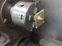
made, simple turning followed by forming the hex shape on the end. With
short items like this I prefer to make a threaded mandrel on hexagon stock,
screw on the item, then index it round in the vice. Holding the mandrel
horizontally, the work self-tightens whereas holding the mandrel vertically
allows the cutter to undo the workpiece. |
 |
 |
The cap was screwed tightly into the steam chest (without
the "O" ring) and the valve rod hole reamed 3mm right through. Doing my
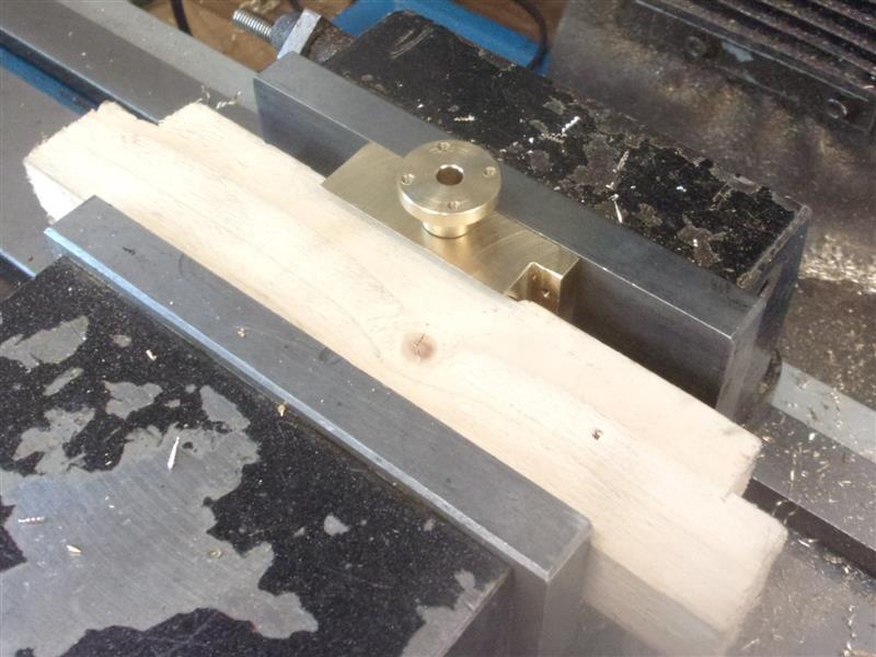
own thing, rather than blindly following the drawing, I reduced a section
of the exhaust pipe to 6.35mm diameter and threaded it 1/4" x 40 tpi. The
steam chest base was drilled and tapped to suit and the flanged pipe screwed
in tight to the shoulder. This does make the exhaust passage smaller than
design but it's not supposed to be a high-revving steam engine, just a slow-speed
pump. The assembly was held in the vice, using timber to clamp on the curved
surface, and the four flange holes drilled and tapped. |
 |
 |
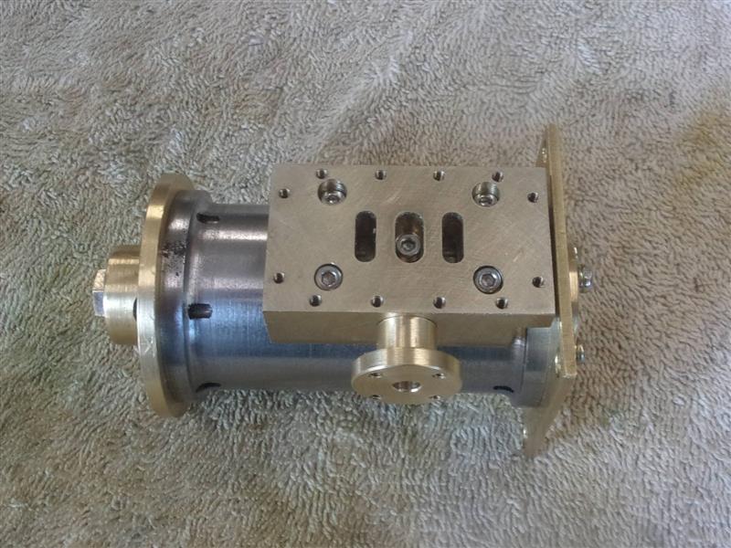
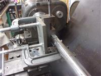
Then the base assembly was bolted onto the cylinder using
five M2.5 stainless steel cap screws. |
 |
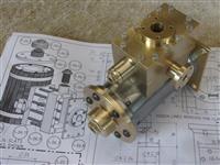 |
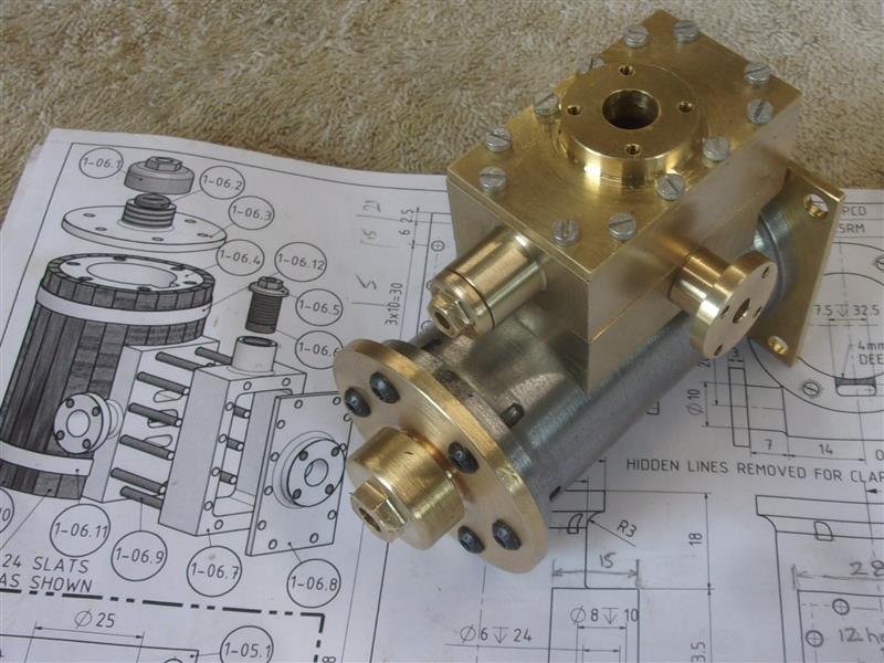
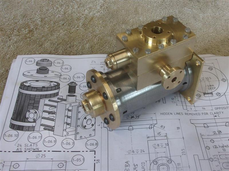
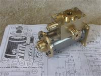
And a couple of pictures of it all assembled. |
 |
| |
6. Piston |
|
 |
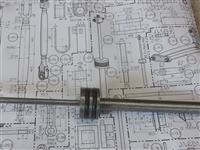
Another deviation from the drawing was the piston. I machined
this from cast iron with a pair of Viton "O" rings to act as piston rings.
They are a bit tight in the cylinder at the moment and I need to deepen
and widen the "O" ring grooves a little. The 10mm diameter pump piston rod
screws into the bottom of the cylinder piston and the 5mm cylinder piston
rod screws into that from the other side. The drawing calls for an M10 thread
and, as I have both taps and a die for M10 x 1, that's what I used. M10
x 1.5 seemed a bit too coarse and would probably throw it off line. |
 |
| |
7. Governor Drive |
|
 |
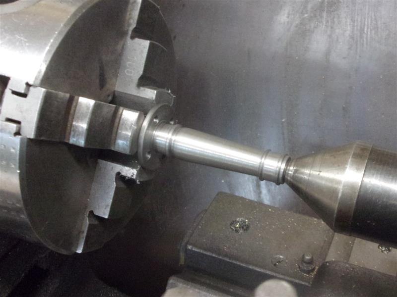
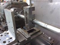
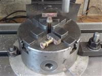
I've made the pillar that supports the governor mechanism
from some spare cast iron that I had in stock. I turned the locating spigot
on the bottom first, then held on the spigot with centre support to machine
the outer profile. A pair of simple bronze bearings were made and pressed
into either end, followed by line-reaming to make the shaft a nice fit.
Here it is placed on the platform before the bushes were fitted. |
 |
 |
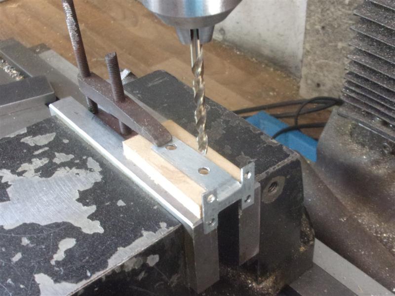
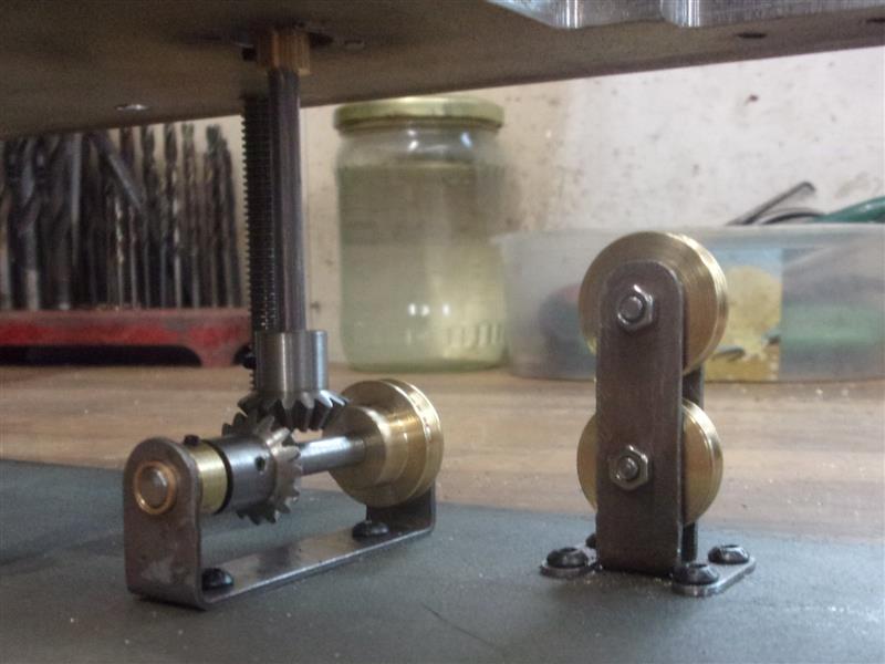
The parts underneath the platform were made next with
the pulley stand being made from some 1mm sheet steel, the basic shape cut
and the feet mounting holes drilled. Then it was folded and clamped around
a piece of 10mm MDF so that the pivot pin holes could be drilled in line.
The vice is just gripping the lower leaf. |
 |
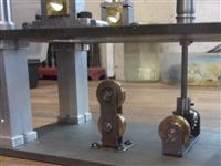 |
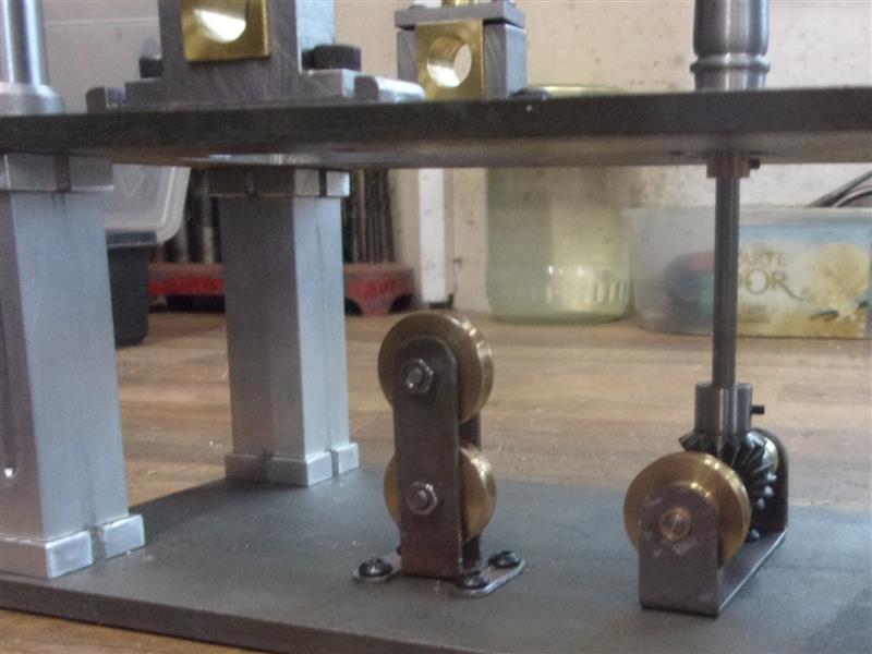
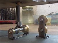
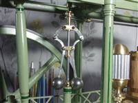
The other support was bent up from the same material and
all the other relevant parts made. This was more like assembling a Meccano
structure with it's spindles, gears and pulley wheels. These are the views
from front and rear. I will dimple the shafts and shorten all the M2 grubscrews
before final assembly. |
 |
| |
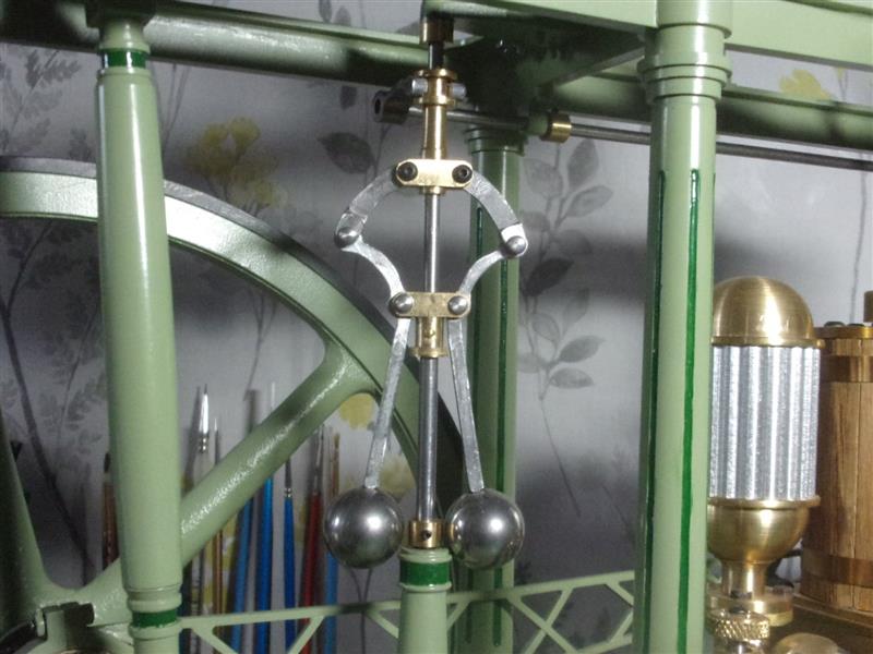
8. Governor |
|
 |
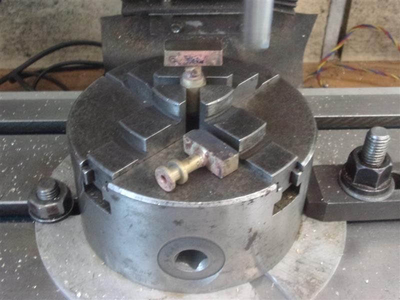
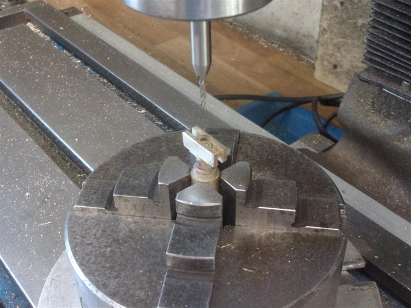
There are a few small parts that make up the governor
and the first of these are the fixed pivot and the moving pivot. I made
these by silver-soldering a square block to the two turned parts that fit
to the spindle. The upper, moving pivot is resting on the chuck after milling
the block to size. A 2mm end mill was used to machine the slots for the
arms. |
 |
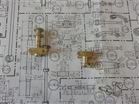 |
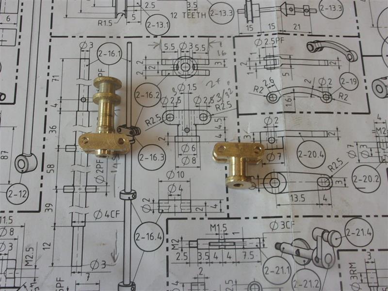
These are the two finished pivots. The lower arms were
cut and filed from offcuts of 2mm mild steel sheet and the upper arms from
6mm x 9mm bar. The balls, which are commercial-made unhardened stainless
steel, were drilled and tapped M2.5 and screwed to the lower arms. The control
arm at the top was made by silver-soldering various small part together. |
 |
| |
9. Next Item |
|
 |
|
|