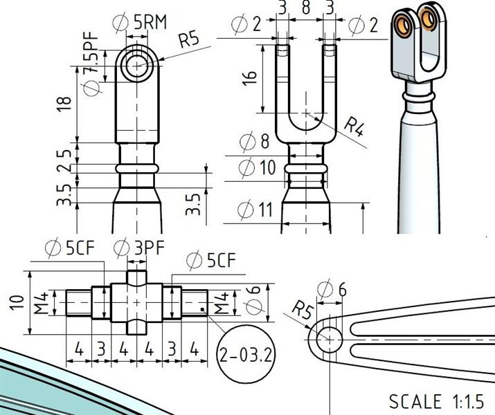
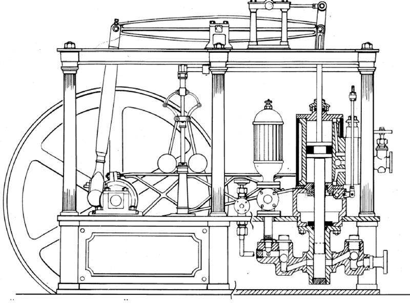
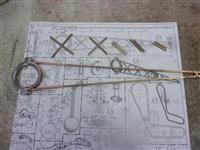
| Motion Parts |
|
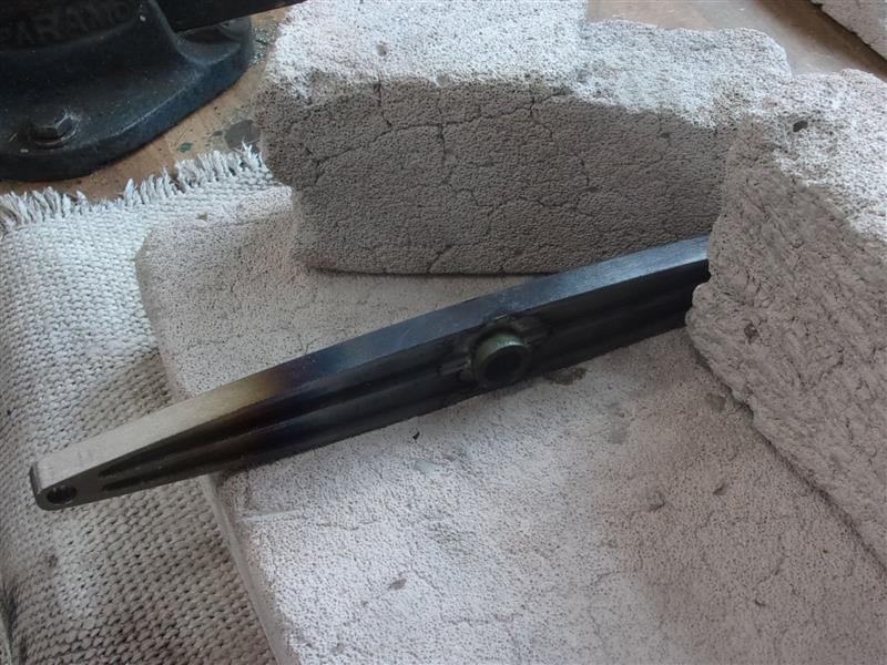
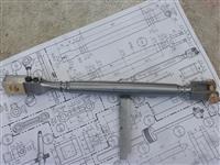
1. Beam |
|
 |
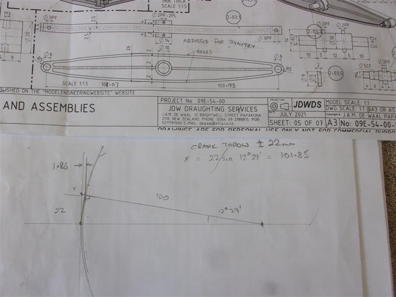
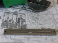
As drawn, the Watts linkage will oscillate between vertical
and 4° backwards but a bit of simple trig shows that the horizontal movement
at the limits is just under 2mm so I've made my beam with 101mm either side
of centre. A few thou here or there will hardly be noticeable. I've also
amended the length of the horizontal linkage arms by half a mil to compensate.
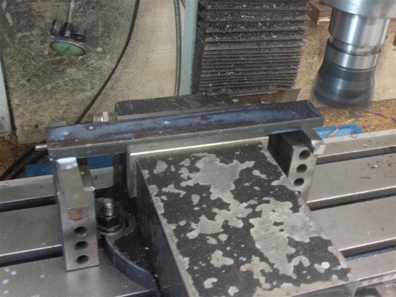
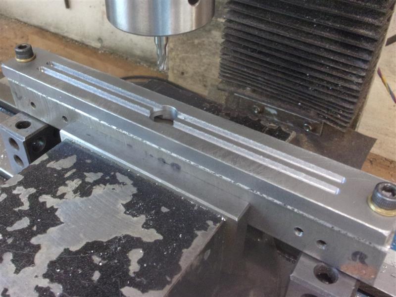
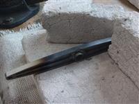
I thought I would have a go at making the beam from solid so the first thing
to do was machine up a piece of 30mm x 10mm black bar to the outside dimensions.
As usual, I'm not using bright mild steel because it will probably warp. |
 |
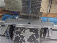 |
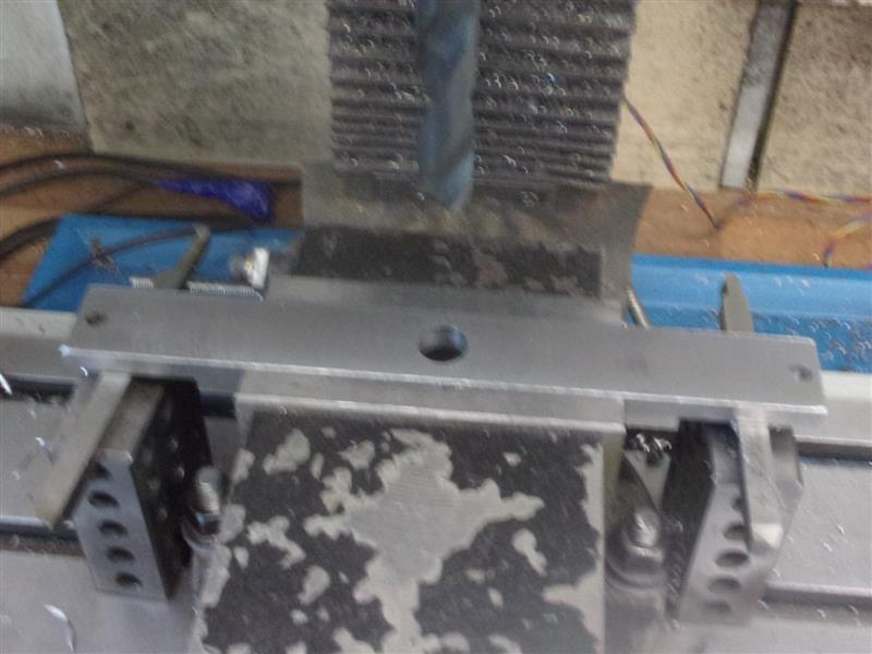
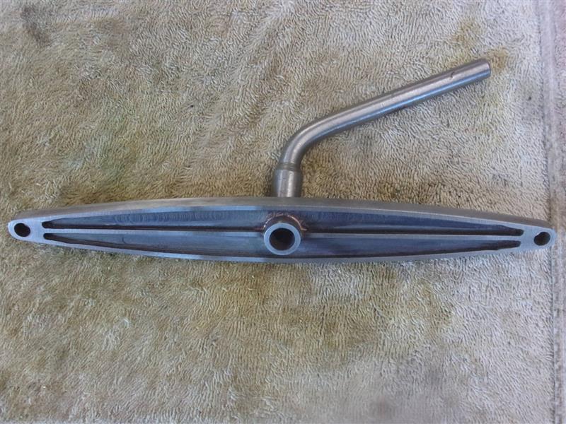
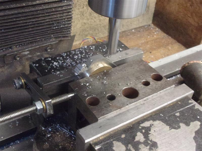
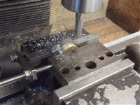
Then the two outer holes were drilled and reamed 6mm diameter
and a central hole drilled 14mm diameter. I intend to silver-solder a boss
in the central hole after I've milled away the inside to leave the central
web. A fixture was prepared with two M6 holes tapped at 202mm centres and
the work bolted on with a packing washer under each end to lift it off the
surface. |
 |
 |
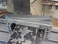
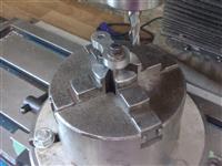
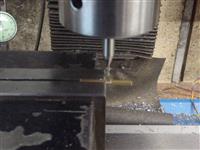
A 4mm carbide slot drill was used to rough out the inside then
I changed to a 3mm slot drill to extend the ends and finish the thickness
of the web. |
 |
 |
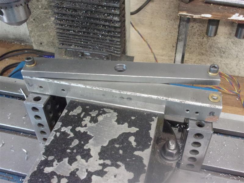
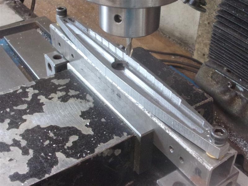
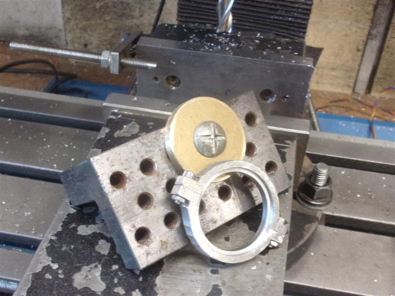
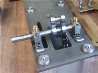
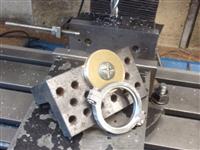
I've been experimenting with some typical Heath-Robinson lash-ups to see if I could come up with a mechanical solution based on the kit available to me and had a certain amount of success and was able to mill the outside shape of the beam in two operations. I took a pictures of a "proof of concept" practice piece but forgot to take any of the finished beam. |
 |
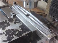 |
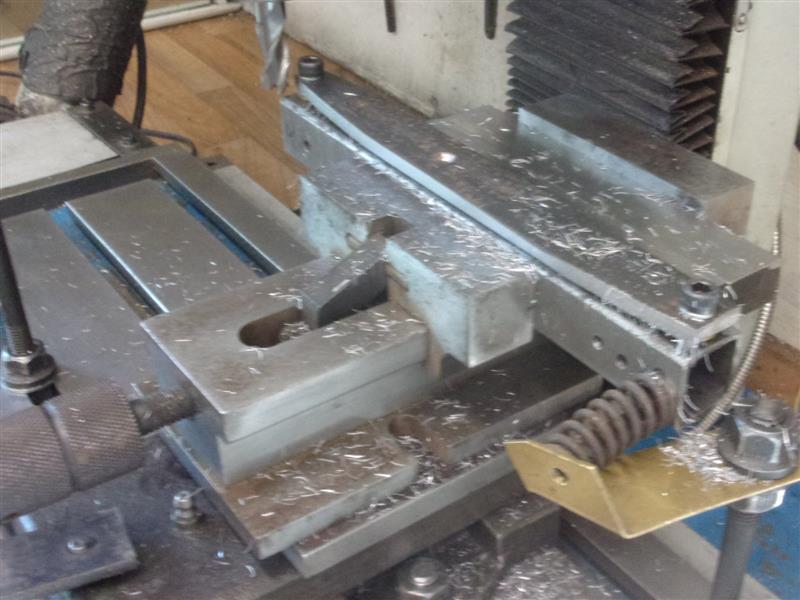
However, the setup wasn't rigid enough to risk a 3mm slot drill with
so reverted to using the DRO arc function. I did some more roughing out
with a 6mm end mill first, though, using the centre of the beam as the
origin. I then offset the "Y" axis to suit the 6mm end mill, set the radius
at nominal plus half the cutter and 0.8mm for the max cut, i.e. step length,
in the "X" axis giving over one hundred plunge cuts per half side. Swapped
to a 3mm cutter for the final 25mm or so and finished all eight end sections. The
boss was made with the bore undersize and then silver-soldered into
place. I will ream that to size later.
|
 |
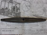 |
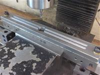
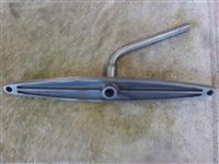
Then it was left in the Phosphoric acid for an hour or
so to clear the flux and blacken the inner surfaces. Finally, a wipe-over
with abrasive blocks to highlight the outer edges. |
 |
| |
2. Crankshaft & Fittings |
|
 |
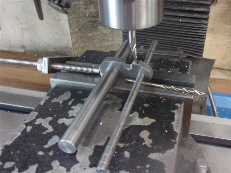
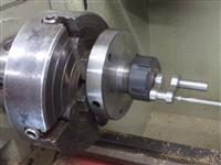
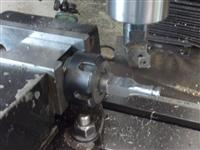
I made the crank arms first, cutting to length, then drilling
and reaming the holes for the shaft and the crank pin. I roughed out the
basic shape first, including removing the waste from the waist. The 2.5mm
drill under the 5mm rod brings them up level. Then I finished the outer
form on the rotary table, mounting each end on a stub mandrel. The drawing
shows sharp corners at the roots of the waist but I've chosen to make the
more traditional shape. |
 |
 |
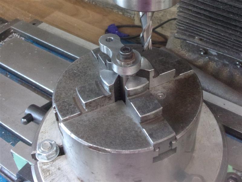
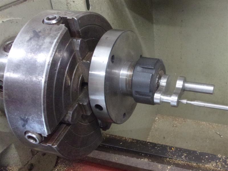
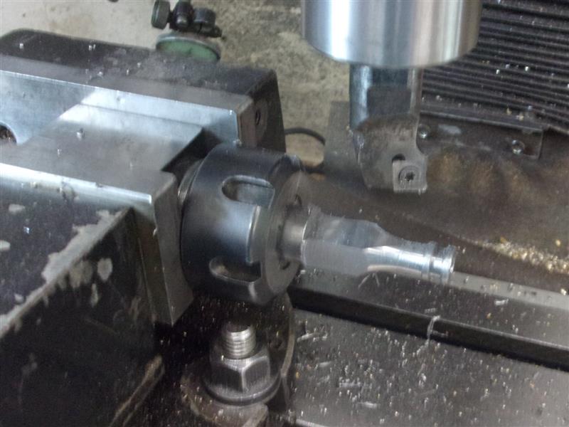
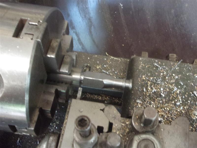
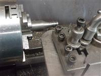
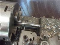
I'm going to silver-solder the arms to the crankshaft
and crankpin and then cut the middle bit out. The crankpin is shouldered
each end to fix the 10mm gap accurately. I set the position along the crankshaft
but wanted to check that it looked right when assembled first. The soldering
went well but I managed to get some on the crankpin and needed to polish
it off. Because I don't have centres in the ends of the crankpin, I had
to find a way to spin it in the lathe because my 6" 4-jaw chuck alone wouldn't
hold it. I used a collet holder in the end. The centre-indicator was just
to get a rough guide. |
 |
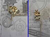 |
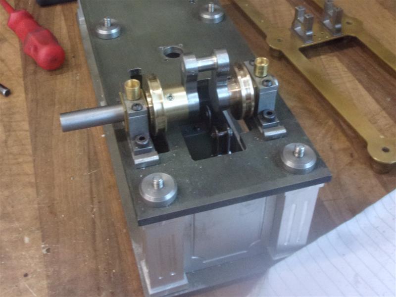
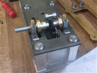
The eccentric and the governor pulley were made next,
the pulley in a single operation and the eccentric by starting with a billet
machined all round to the maximum dimensions along with the groove, then
drilling and reaming the offset bore on the mill and finally mounting it
to a mandrel to machine the two bosses. No process pictures for these, just
the finished items. And, finally, all assembled into the bearings and tested
for clearance. I need to make a thin bronze spacer to fit between the eccentric
and the rear bearing to take up the end-float but, otherwise, this bit is
finished. |
 |
| |
3. Crank Connecting Rod |
|
 |
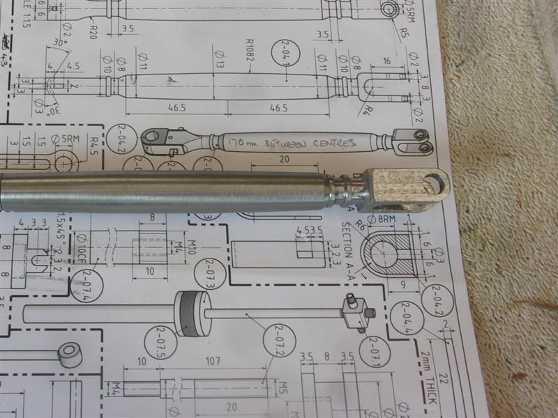
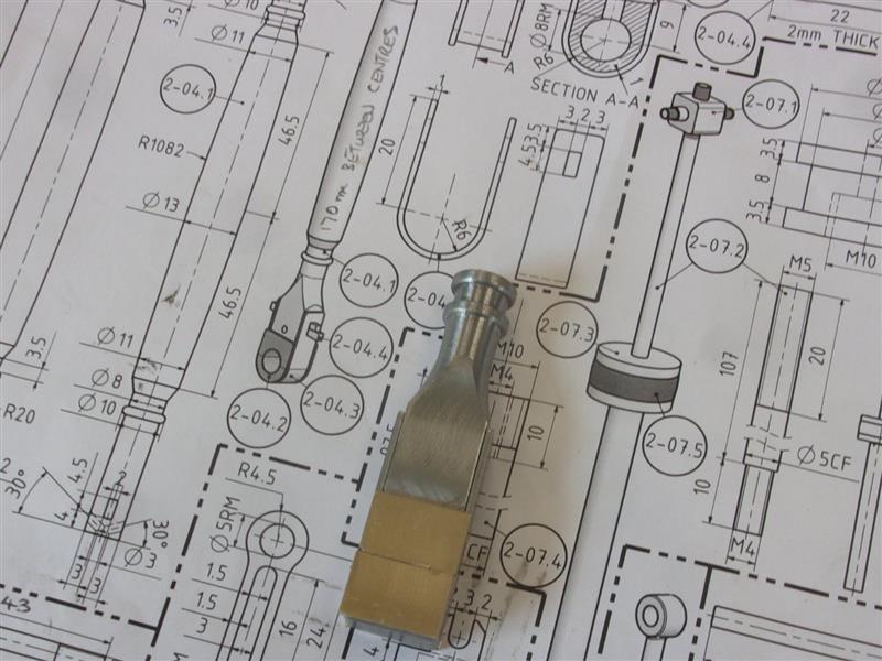
I've made the crank connecting rod in three parts, the
main stem so that I could turn it between centres and the two ends, one
screwed in and one pressed in. I set the compound slide over to about 2°
and turned the stem to half-way, then turned the stem round and did the
same on the other end followed by blending in with emery cloth. The top
clevis had all the fancy turning put on it and then the two parts were screwed
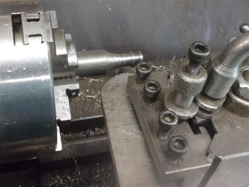
together with a short length of M5 all-thread. For the other end, I started
by making the decorative part first, using a large radius form tool to create
the curve. |
 |
 |
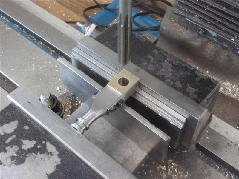
Then I transferred the bar to a square collet block and
milled the rectangular lower section. Then it was back to the lathe and
parted off to length. |
 |
 |
For the bearing, I milled up a pair of bronze blocks 10mm
thick with an 8mm groove milled round three sides for the strap. The strap
was made from 1mm thick mild steel and folded for a tight fit around the
blocks. After drilling the strap-fixing holes, the parts were clamped together
with M3 screws. Then it was flipped sideways and the bearing hole drilled
and reamed 8mm diameter. I haven't bothered to try and create the rounded
shape at the bottom because, for static display, the crank will be positioned
to hide that feature. |
 |
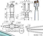 |
One thing of interest is how Julius has designed the coupling
at the top. As drawn, assembly and, particularly, disassembly would be somewhat
awkward. Anyway, I've chosen to use a bronze clevis pin with a bronze collar
for the upper coupling even though the more common method would be a bronze
bush in the beam and steel clevis pin. |
 |
| |
4. Eccentric Strap |
|
 |
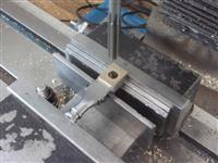
The eccentric has been made from bronze so I made the
eccentric strap from two pieces of mild steel flat bar. They were milled
on the outside to get the clamping shoulders made, then bolted together
with M2.5 cap screws and nuts to turn the bore. To mill the circular outside
form, I made a simple fixture on a small angle plate and rotated the strap
around the boss. Then the corners were filed and the outside polished up
a bit. |
 |
| |
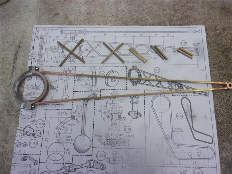
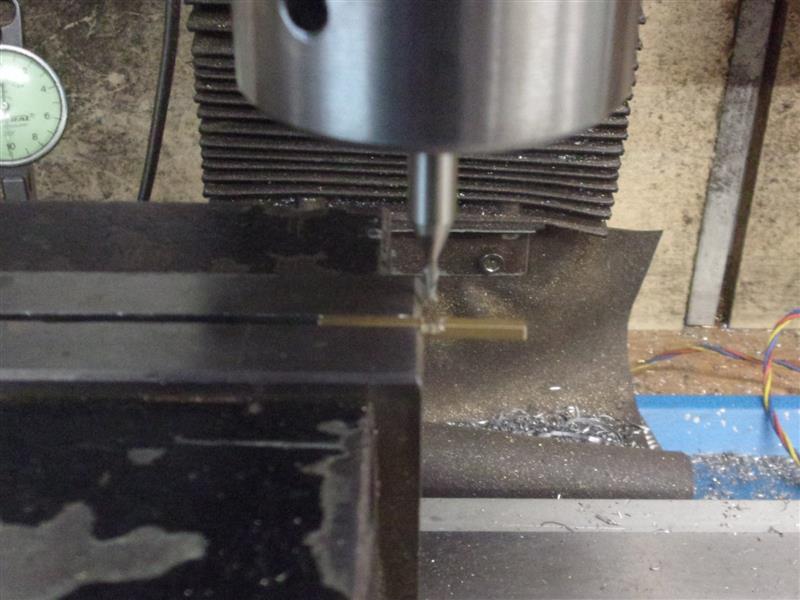
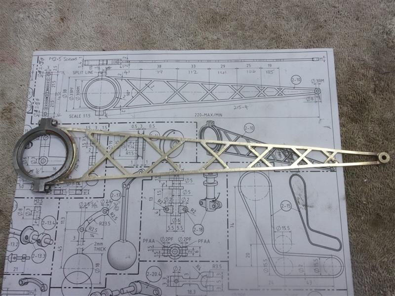
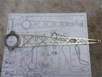
5. Eccentric Rod |
|
 |
The eccentric rod is a lattice framework, silver-soldered
together and with an eye at one end. The lattice has been made from 2mm
square brass rod and all the joints are butt-jointed except for the cross-braces
which have been half-lap jointed in the middle. The two outsides and the
eye were soldered together first. The crossbars were cut over-long ang the
middle marked with a felt-tipped pen. They were held at the end of the vice
and aligned by eye and a 2mm end mill used to cut the slots. |
 |
| Starting at the narrow end, the first cross was filed
to fit into position then soldered into place. Once cool and cleaned up
the second cross was done, and so on until complete. Finally, the curved
piece was shaped and fitted to the eccentric strap. Not wanting to disturb
the lattice frame by overheating, I soft-soldered this last piece into place |
 |
| |
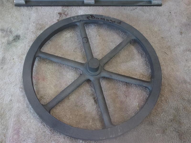
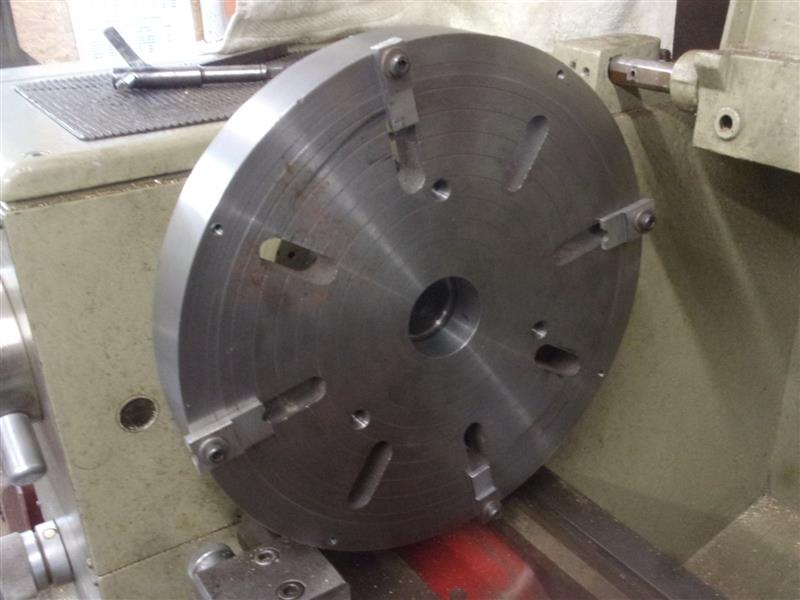
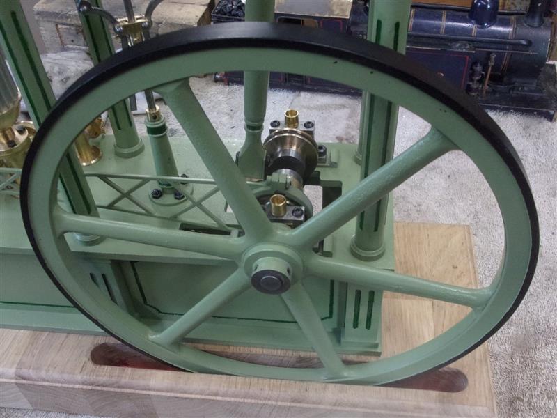
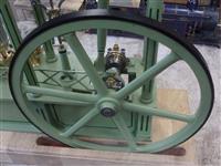
6. Flywheel |
|
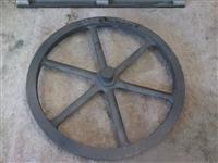 |
I have used a cast iron flywheel that differs from the
drawing but covers the important dimensions. It has some damage but I will
machine this out or use filler where neccessary. I mounted the flywheel
to a large faceplate for the first operation, machining the o/d and facing
the front. However, because the spokes are dished outwards on one side,
when I tried to turn over and do the other side it wobbled around and I
had to make some stand-offs for the faceplate. |
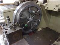 |
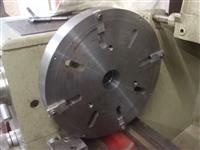 |
These were clamped to the faceplate and machined to suit
the o/d of the flywheel, meaning I didn't have to clock it out for the second
op. The flywheel was then remounted and the other side faced off, the boss
faced, drilled, bored and reamed to size, then reversed again and the other
side of the boss faced to length. It wasn't worth trying to put a keyway
through the boss because there is no load on the flywheel so two grubscrew
holes were drilled and tapped on the outer boss to secure the flywheel to
the crankshaft instead. |
 |
| |
7. Next Item |
|
 |
Under Construction |
|