| Assembly and Alignment |
|
This section is for anything directly related to the assembly of the
locomotive, or any sections that needed reworking to make them fit.
|
| 1. Bogie Assembly |
|
|
 |
All the various parts have been assembled
and set into place followed by lowering the axle onto the springs and bolting
the keeper plates into position. I have used a 2-part epoxy adhesive to
fix the pressure pad cups to the axleboxes but they should be captive now.
I have set MDF packing pieces between the axleboxes and the top of the horns
to set the simulated ride height and I now need to adjust the guard irons
for height because they are fouling the rail at present. |
| 2. Wheel Assembly |
|
|
 |
I made the keys for the main wheels from 1/8" square
keysteel, just cutting them off at 5/8" long with a junior hacksaw.
I then carefully dressed them with a needle file and emery cloth until they
were a snug fit in the slot in the axle. I also had to make some brass spacers
to put between the bearing face and the back of the wheels because the shoulder
on the axle is not large enough to get a firm fit against when pressing
the wheels on. |
| Next I pressed in all the crank pins, made sure they were
all seated properly and finally pressed the wheelsets together. Everything
was about half a thou interference fit and is unlikely to come apart in
use. The effort needed to press them together was greater than my small
driller could handle so I took all the parts to my local car workshop and
got them to press everything together with their twenty-ton press in exchange
for some universal beer tokens. The only modifications I had to make was
to thin the axlebox covers down a little to ensure that there would be no
fouling on the back of the wheels. |
 |
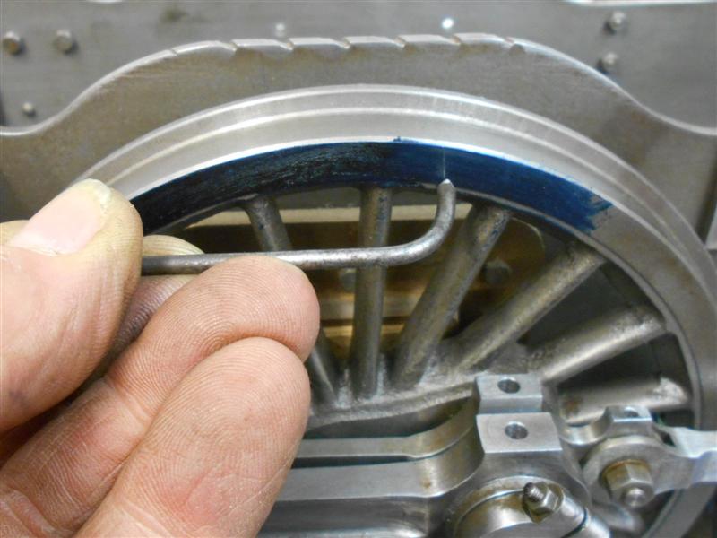
| 3. Finding Dead Centres |
|
|
 |
I found an article by an American gentleman, Jeffrey G.
Hook of the Deerfield and Roundabout Railway describing finding dead centres
and I have followed his procedure on Britannia. If anyone wishes to read
his original article I have created a link in the "Links" page.
Packing pieces are set on top of the axle boxes to simulate the correct
ride-height in normal operation. I started by making a wheel tram from a
piece of tough 3mm dia steel and choosing reference points on the loco to
locate the tram. I chose to use the expansion link brackets and set a small
dimple in each one accordingly. I worked on the driver's side first, rolling
the loco along the bench until the crosshead was at the far right in the
slidebar brackets and blued up the top quarter of the driving wheel. Then
I rolled the loco forward about an eighth of a turn of the wheel and zeroed
the DTI on the front of the crosshead. |
 |
 |
Using the wheel tram a line was scribed across the rim
of the wheel. The loco was then rolled backwards until the crosshead "turned
the corner" and came back to the same reading on the DTI. At this point,
a second line was scribed on the wheel rim. I then repeated the operation
for both lines to check that nothing had moved whilst rolling the loco back
and forth. Using a digital caliper, I scribed a horizontal line across both
perpendicular lines and set a tiny dimple at the two intersections. Using
a pair of dividers, I scribed two more arcs to nearly meet in the middle
and marked the horizontal to these arcs also. |
 |
 |
An indent was made between the arcs on the horizontal
line and when the wheel tram is placed in the indent and rested in the reference
point, the wheel is exactly on back dead centre. To find the front dead
centre, the procedure was followed again but with the crosshead at the front
of the slidebars and the clock measuring from behind the crosshead. The
loco was then turned round and the exercise repeated for the other side.
Now that I can accurately find the dead centres I can move on with setting
the return cranks to their correct positions. After that, the wheel tram
will be put in a safe place to ensure it can't be found if it's ever needed
again. |
 |
| 4. Setting the Return Cranks |
|
 |
Following on from the procedure of finding front and
back dead centres, the next process was to find the correct position for
the return cranks. Once again I followed the information provided by Jeffrey
G. Hook and started with the driver's side by setting the loco in neutral,
the position where the die block at the end of the radius rod is exactly
in the middle of the expansion link. Rocking the expansion link back and
forth creates no movement of the radius rod in this position. A while back
I made an adjustable, sliding gauge for marking out the coupling rod centres
and this was used to set an approximate length of the eccentric rod as shown
on the drawing. The gauge has a pair of bushes with 1/8" diameter holes,
and two pins were made to fit into the return crank and the tail of the
expansion link respectively, with 1/8" diameter spigots to fit the gauge. |
 |
 |
The expansion link moves back and forth from
vertical at the front dead centre position to fully tilted in one direction
at middle dead centre, then onwards to vertical at rear dead centre and
finally to fully tilted in the opposite direction at the other middle dead
centre position. By setting a DTI on the expansion link, it is possible
to measure the positions of both front and back dead centres quite accurately.
When the two readings are the same, the return crank is exactly 90 degress
to the centreline of the motion. Using the trammel from earlier, the loco
was positioned at front dead centre and the clock set up as low down as
I could. The loco was then wheeled backwards to the back dead centre position,
keeping an eye on the clock. In my case, it came nowhere near contact with
the stylus so the return crank clamp was loosened and the crank rotated
until it just touched the stylus. The clock was moved until a zero reading
was obtained and the loco was then wheeled forwards until I reached the
front dead centre position again and a note made of the clock reading, which
had slightly over-ran the FSD of the clock. |
| This back and forth process was repeated a
number of times, adjusting the crank and the clock until I attained the
same reading on the clock at both dead centre positions, probably about
nine or ten cycles in all. When I got to the point where I was getting less
than one thou difference on the clock for both front and back dead centres
I called it a day and locked the return crank clamp up tight. I also took
the opportunity to pin the lifting arms to the weighshaft with 3/32" taper
pins, pinning the driver's side first. The link was set exactly in mid-gear
and the lifting arm on the fireman's side adjusted until this link was mid-gear
also. After marking the position, the firman's side was also drilled, reamed
and pinned. The crank on the fireman's side was then set, leaving (I thought)
only the eccentric rods to be made to finish the motion. Then it all went
pear-shaped. I also realised that I would not be able to fit the eccentric
rod pins after assembly so these were made and fitted before continuing. |
 |
| 5. Eccentric Rod |
|
|
 |
The eccentric rod needs to be made to suit
the rest of the motion and differs by a small amount on each side of the
loco due to machining tolerances. The distance between the bushes in the
eccentric rod are correctly spaced when the loco is placed on either dead-centre
and there is no movement of the valve when the radius rod is raised and
lowered in the link. The distance gauge was set up as before, the locking
screws released and the link pin removed from the bell crank to allow the
radius rod to be moved freely. The gauge was adjusted until the condition
above was obtained and the gauge locked up. This distance between the bushes
was accurately measured on the mill with the DRO and this reading used to
make the first eccentric rod. The procedure was repeated for the other side,
with a slightly different reading obtained for the second bush spacings. |
| 6. Return Crank Pin |
|
|
| Whilst setting up the second eccentric rod
the link hit the expansion bracket (see item 8) and managed to move
the return crank which meant I had to reset the position. Upon closer inspection
it turned out that the driving crank pin was not as tight a fit in the wheel
hub as I thought. From all that I've read, this appears to be one of the
most important parts of the motion and I didn't fancy it moving again in
service. I decided, therefore, to disassemble the driving axle and fix the
two crank pins to ensure they stay exactly where they are but can be removed
for replacement if ever neccessary. To this end, I have drilled and tapped
an M3 hole at the interface, counterboring to take a cap-screw head purely
because I have loads of them. I would have just used a grub screw otherwise. |
 |
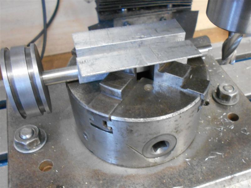
| 7. Cross-pinning the Return Crank |
|
 |
Because I could see no way of pre-determining the position
of the return crank, I knew there would be a problem pinning them after
final adjustment. I didn't want to use a hand-drill to drill through and
I couldn't see how the assembly could be dismantled without losing the position.
I decided to pre-drill part way through the return crank and, after setting,
take the whole axle to the mill to complete. I started by setting up a piece
of 3/8" dia material in the milling vice and using this as a reverse drill
jig to drill a 3/32" dia hole through the first side only of the return
crank. The cranks were then set as described previously and locked up tight
with the clamp screws. All three axles were then released from the frames
and the coupling rods separated from the front and rear wheels. |
 |
 |
The centre axle, complete with the front coupler and the
con rod, was then taken to the mill and set up on parallel risers to enable
rotation of the wheelset. A 3/32" dia drill was used to get the pre-drilled
hole in the crank vertical and the assembly clamped to prevent movement.
The drill was then passed right through, followed by a 3/32" taper-pin drill
and finished with the matching reamer. Finally, taper pins were trimmed
to size and fitted to both cranks. The axle was then returned to the frames
and the wheeltrain reassembled. |
 |
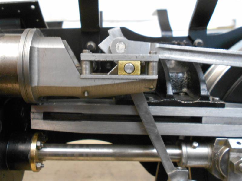
| 8. Expansion Link Brackets |
|
 |
The driver's side wheel fouls the expansion
link bracket if the suspension is bottomed out. The drawing shows a slope
to the offending area but this is nowhere near enough to clear the wheel.
No dimensions are given, either. I have used a 12mm endmill to remove a
section of the bracket to ensure the wheel has clearance at all times. I
later found that the fireman's side requires a similar modification. It
also needs a section cleared away where the link fouls the bracket on the
return stroke. |
 |
| 9. Cylinder Adjustments |
|
|
| After bolting the cylinders on for what is,
I hope, the final time I set about getting the length of the piston rods
correct. I dismantled the end covers from the cylinders and removed the
rings from the pistons to make it easier to work. I also found it easier
to remove the slide bars and slide bar brackets leaving the crossheads floating.
The driver's side piston rod was about seventy thou too long and causing
fouling of the front cover so this was removed on the mill. I didn't want
to break down the chuck that was on the table so used it as a vice instead.
Another use for a 4-jaw chuck! |
 |
 |
After checking that there was equal clearance
at both ends of the cylinder, I removed the crosshead from the con rod and,
with the piston rod located in the bore, the two parts were cross-drilled
and reamed to accept a 3/32" dia taper pin. The fireman's side was
much the same and it's probably where I made the crossheads to my own design
rather than follow the drawing. On reassembly, I found that one of the slide
bar brackets was still a smidgeon too low and putting undue pressure on
the piston rod so the mounting holes in the frames were opened up a little
more and the bracket clamped up tight where it wanted to naturally sit.
It all slides as smooth as silk now. |
| 10. Expansion Link Tailpin |
|
|
 |
During assembly of the final part of the motion, it was
obvious that the clearance between the eccentric rod and the con rod was
going to foul the head of a clevis pin. Therefore, I decided to make a pair
of short pins and hold them in place with tiny grub screws. A new hole was
drilled and tapped M3 in the bottom of the expansion link, and the oil holes
were put in at the same time - I had forgotten to do them previously. |
 |
| 11. Valve Guide Clearance |
|
|
 |
Pushing the loco back and forth along the bench
with the reverser in mid-gear, I noticed that the clearances of the die
blocks at each end of the valve guide were different when on opposite dead-centres.
On the driver's side the gap between the die block and the front endstop
was 0.146" and at the other it was 0.122". To get these readings
more equal, the combination link was removed and a small set put in it to
compensate. On the fireman's side, it was the other way round, the front
clearance was 0.101" and the back clearance 0.165". For this side,
it was easier to move the whole valve guide nearer to the cylinder. This
was achieved by taking the valve guide to the 4-jaw chuck and facing another
thirty two thou off the rear face. |
| 12. Setting the Valves |
|
|
 |
Whilst making the cylinder valve liners and
the bobbins, I deliberately made sure that the length dimensions were as
accurate as I could make them. Because of this, I was able to make the preliminary
valve settings quite easily. Working on one side at a time, I first screwed
in the valve stem, without the valve bobbin, into the valve crosshead about
half way and locked its position. Next, I set the loco on back dead centre
using the wheel tram and accurately measured from the front of the valve
liner to the front of the valve stem, noting the dimension. The loco was
than rolled forward to the front dead centre position and the measurement
repeated. Taking the average of these two measurements gives the exact mid-point
of the valve travel and the loco was rolled backwards until exactly at this
midpoint. Because I know the overall length of the valve liner and the length
of the bobbin, I can calculate the position of the front of the bobbin relative
to the front of the valve stem. Without moving the loco, the valve stem
was then removed and the locknuts and bobbin loaded on. |
| After much fiddling around, I managed to get
to the point where the bobbin could move radially about the valve stem but
with only about a thou end-float and the distance from the front of the
bobbin to the front of the valve stem within a couple of thou of the calculated
dimension. The valve assembly was then reloaded to the cylinder and the
valve stem screwed into the valve crosshead until the bobbin measured 1.437"
from the front of the valve liner. The valve stem was then locked in this
position and the valve should now be at the correct position. This procedure
was then repeated on the other side. I don't know whether this is the correct
way to set the valves but, as the short video on the "Overview" page shows,
after lashing up a temporary air supply, the loco worked "straight out of
the box" so to speak. It's all very tight and a bit jerky at the moment
but I am going to set up a more substantial air supply and set it running
for a few hours to try and run it in. After that, if the valves need tweaking,
the motion should run a little more freely. |
 |
| 13. Smokebox Rivets |
|
 |
The smokebox rivets have now been fitted with the exception
of the top and bottom ones at the front. These will be round-headed screws
and are to retain the smokebox door ring in position but allow removal at
a later date if required. The door ring is a good fit but not tight enough
to stay there on it's own. First, all of the rivets were fitted in the traditional
manner - my fancy home-made rivet squeezer was not up to the job although
it works well with softer copper rivets - banging into pre-formed countersinks
on the inside and then dressed back to flush with sanding drums in the Dremell.
Next, the door ring was pushed into position, lining up the scribed marks
at the bottom, and the assembly mounted on the mill. The two holes were
then spotted through followed by drilling for 10BA and tapping freehand.
The first picture shows an offcut of a RSJ that I spotted in the skip at
the local forge and this came in really handy for supporting the smokebox
during drilling. |
 |
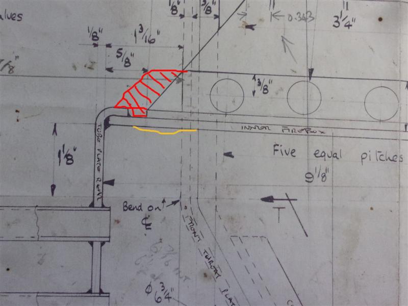
| 14. Boiler Mods |
|
|
 |
During the shell test, the crown deformed slightly where
the yellow mark is due to the softness of the copper. If the girder is extended
as in the red mark then the flange would provide additional support because
of the double thickness. |
|
| 15. Removing the Grate |
|
|
 |
I have redesigned the ashpan so that the grate comes out
in it's entirety quite simply. Allowance has already been made for pipework
and the injector in this area. The first photo shows the left-hand side
of the ashpan. The lever is for the drop-grate feature and is in the grate-up
position. The two bars on view are the cross-bars that the grate rests on.
To remove the grate, I first drop the grate to it's lowest position and
then remove the three screws circled. Sorry, the focus is a little out here. |
 |
 |
The top panel of the ashpan then rolls forward and out.
The grate support bars are now on view. The larger diameter with the ends
turned round is so that the grate gets lifted up into the firebox rather
than sit slightly below it. The ashpan panel has a support strip silver-soldered
to the back and is drilled and tapped in three places. The redundent hole
near the rear support slot was in the wrong place, when the crossbar was
here, the grate wouldn't drop fully. It's now an additional air hole. The
longer spigots on the support bars stick out to the left and allow the grate
to be shaken slightly up and down to help clear ash from the bars. |
 |
 |
Before the two support bars are withdrawn, a stiff 12"
rule is placed underneath the grate to allow withdrawal. This is a spare
one from adjustable square and is thicker than a normal rule. And, finally,
a shot of the grate out of the loco. Because the grate rolls forward down
the support bars, a couple of extra spacers (circled) were added to ensure
the grate stays centrally within the box. Replacement is just a reversal
of these steps and takes less than five minutes. Not too onerous a procedure,
I would suggest. |
 |
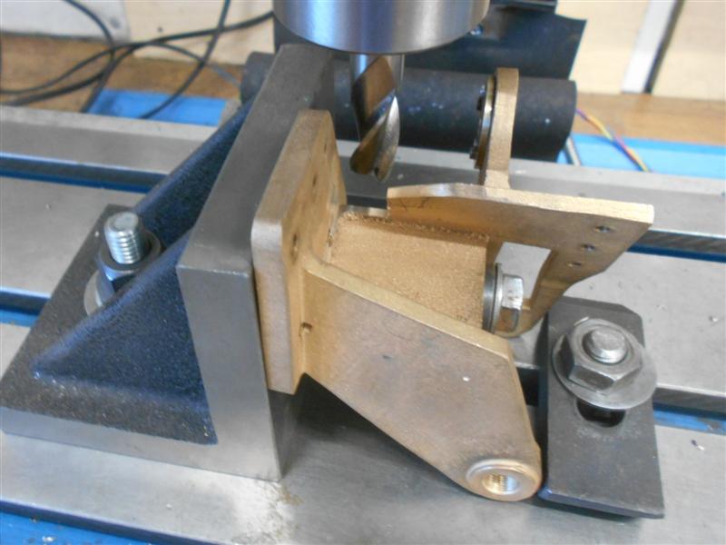
| 16. Cylcock Operating Gear |
|
|
 |
The holes in the frames for carrying the cylcock operating
shaft are too close to the cylinder, causing the outer forks to foul the
gland housings. Because the holes were already drilled, I chose to make
a pair of brackets that locate on the edge of the frames and are fixed using
the lowest cylinder backplate bolt. Once painted black, they will be all
but invisible. A note has been made on the "Errors" page. |
 |
| 17. Regulator Linkage |
|
|
 |
For some reason or other, the regulator spindle was not
in line with the stuffing box in the smokebox casing so, rather than try
and remake parts to fit, I made a peg and lever arrangement to operate the
valves. The 3/16" dia stainless steel peg is fixed in a 1/4" x
5/16" brass lever fitted to the end of the driving shaft. The peg runs
in a 3/16" channel milled into a piece of 1/4" x 3/8" brass
which, in turn, is fitted to the regulator shaft. 8BA screws clamp the brass
components to the shaft and allow for adjustment in both planes. |
 |
| 18. Oil Pump Removal |
|
|
| As drawn, it would be impossible to remove
the oil pumps for repair or replacement without removing the boiler. Because
of this, I have dispensed with the two rear fixing screws and fitted catchplates
to the oilpump platforms instead. They are about 7/8" long and made
from 3/8" x 1/8" flat mild steel with a rebate milled away at
the front, equal in height to the base of the pumps. A pair of 8BA screws
fix them to the platforms. |
 |
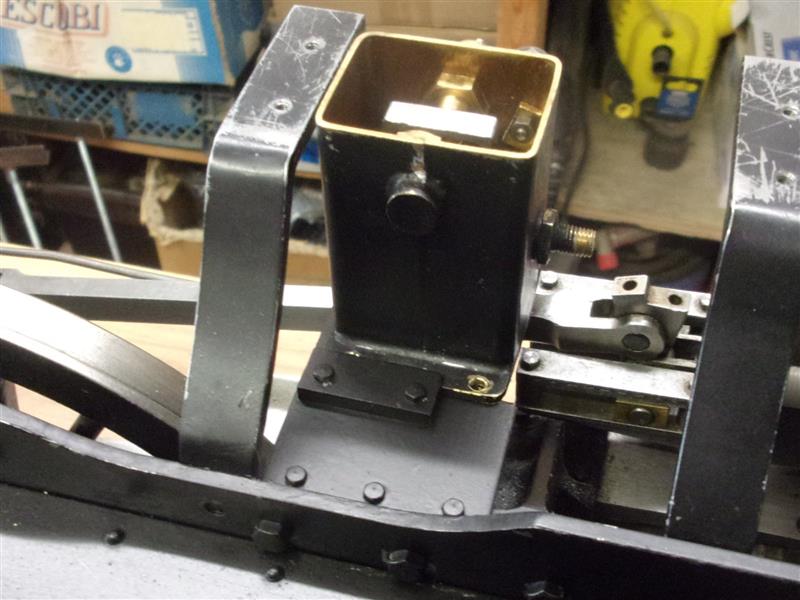
| 19. Axle Pump Oiler |
|
|
 |
It is difficult, if not impossible, to get
oil to the eccentric of the axle pump. My solution was to put an oil dashpot
on the upper stretcher connected to the eccentric with a length of flexible
plastic tube. This has a 1/8" dia bore and is used as an oil feed in
chainsaws and similar. It is also very pliable. By placing the dashpot just
behind the weighshaft, it is fairly easy to flick the lid open and fill
the reservoir with oil. |
| 20. Firebox Safety Clips |
|
|
| Although the boiler is fixed to the frame
at the smokebox end, the draughtsman does not offer any means of fixing
the firebox end. Because of expansion, the boiler needs to slide on the
ashpan and I have chosen to make a pair of clips that screw into the foundation
ring and fit below the rear support bar. The clips are about 1/2" wide
x 1" long each leg and held with a 4BA steel screw but I may get some
cap screws for this. I have also removed a section of cleading to allow
them to be fitted after the boiler is seated on the frame because the blowdown
pipe stops the boiler being slid into position. This is probably not enough
to keep the assembly together in the event of an accident (such as falling
from a high-level track) but should stop it separating in the event of a
minor spill like tipping over in the car. |
 |
| 21. Next Item ... |
|
|
| |
|
|