| Drawing 11 - Smokebox
|
| 1. Smokebox Tube |
|
|
 |
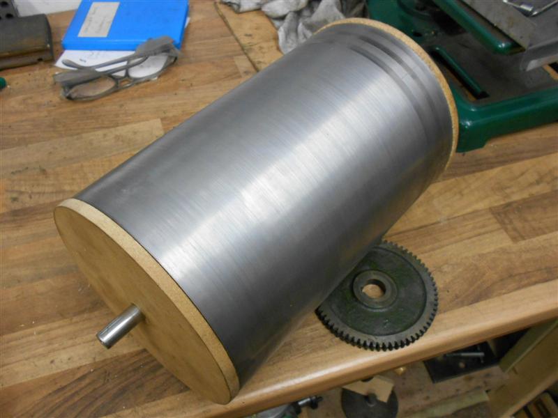
I have made my smokebox from a length of 6.5/8" diameter
CDS2 tube that started life as 1/4" thick wall and which I had reduced to
1/8" wall (10 swg) by the supplier. This was primarily to reduce the weight
and I told the supplier that size and finish were unimportant. This made
the length of tube much easier to handle but, conversely, a little more
flimsy. It's a large smokebox finishing at nearly 10" long. To assist machining
this rather large lump I have recently made a couple of special tools, a
large fixed steady and a large pipe centre that I have covered in the Tools
pages. That just left the headstock end to be catered for (or so I thought)
and, after a tentative start and a minor panic when things went slightly
awry, I stepped back and had a rethink before I made a pig's ear of the
job. The first task was to make up a set of decent soft jaws to clamp down
onto the work. |
 |
 |
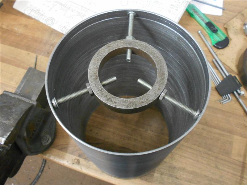
Following my first exploratory cut, I found that I was
making the tube triangular-shaped with the jaw pressure, and this sprung
back when the jaws were released, leaving the tube the same triangular shape
instead of perfectly round and, once again, the fixed steady was unable
to handle the shape. To get around this, I modified one of my clamping rings
to sit inside the tube and give the soft jaws something to clamp down onto
without distortion. |
 |
 |
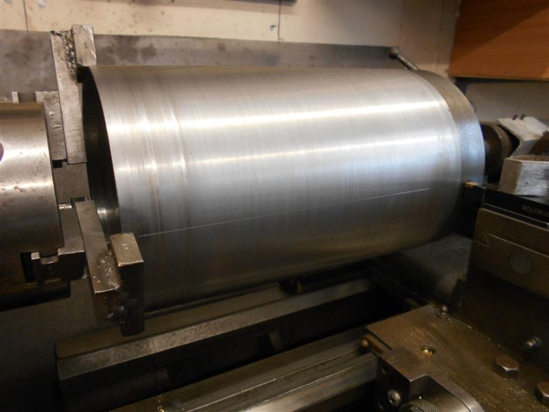
Another problem that became apparent was that the tube
was not perfectly round inside either, and when I squeezed the live centre
up, that too was distorting the tube which relaxed on release. With the
tube trapped inside the fixed steady but not under pressure from the rollers,
a small chamfer was carefully put on the inside diameter. To stop the work
bouncing around I ran the lathe at about 60 rpm and applied some downwards
pressure to the tube with a baulk of timber. Now everything could be clamped
up tight and the O/D skimmed for a full clean-up and no distortion when
releasing the work at the end. After the final cut I dragged the tool back
along the component to leave a lightly scribed line. I shall use this as
the lowest-point datum when I set up to machine all the holes. Now able
to use the fixed steady effectively, I faced off one end of the tube and
cleaned up the bore for about 1/2" long, no particular size - the smokebox
ring or boiler packing ring will be made to suit. Chatter was still a bit
of a problem but a length of emery cloth wrapped around a stick cleaned
out most of it. The tube was then reversed and the same done at the opposite
end but finishing the length at 9.15/16". |
 |
| 2. Smokebox Ring |
|
|
 |
I have be made my smokebox door ring from some bronze
plate, athough I'm not sure what grade it is. This is what I'm starting
with, the piece being 6.3/4" (170mm) square and 1/2" thick. First job was
to saw off the corners to make for easier holding in the chuck, and three
quaters of an hour later, I was able to load the work to the independent
four-jaw chuck. Now, I want the lump from the middle but didn't fancy trepanning
this so had a cast around the workshop and found my 110mm holesaw. Perfect. |
 |
 |
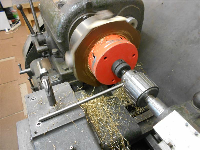
Because I don't want a hole in the middle of my trepanned
billet, I set the saw up without a pilot drill, which meant everything had
to be pretty tight at the start. Here, I've just got underway and experimenting
with speeds, settling on about 60rpm as optimum. On my lathe, the tang on
the drill chuck sits in fresh air, and the chuck was creeping round in the
2MT socket, hence the 5/16" bar in one of the keyholes, resting on the tool
carrier. You can see by the swarf that it's a bronze, brass would chip.
I'm using a home-made version of neat cutting oil to assist the cut - a
mixture of Rocol RTD paste and undiluted soluble oil, mixed to a runny slurry. |
 |
 |
It took about ten minutes to get through the billet, but
here I've backed out from the work on completion. And here are my two billets
ready for their respective jobs. The reason I've covered this in detail
is because it shows that unusual tools can be used in the right circumstances,
or a tool used in a different manner to achieve the desired result. In this
case, a holesaw on a lathe without a centre support which wouldn't normally
be considered suitable. Did the job, though. |
 |
 |
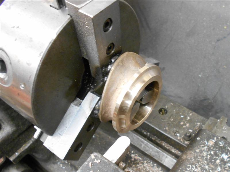
This was subsequently loaded to the 3-jaw chuck, faced
off and the O/D roughed out. The soft jaws used for the smokebox tube were
then set in the chuck and the ring reloaded, facing off to just over finished
length and then getting the bore to final size. The drawing also shows a
recess with a radius in the corner and this was finished with a radiused
form tool. The workpiece was now reversed onto the inside jaws and the front
faced to length, the O/D skimmed to final size and the external radius put
on with a form tool, finishing with some emery cloth on a rule to blend.
Staying with these jaws, the ring was reversed once more and the locating
spigot turned to size. |
 |
 |
This was made to be a good, tight fit to the bore because
I will want to be able to remove it when in service but I don't want it
leaking like a sieve and destroying the slight vaccuum that gets created
in use. I'm using an ultra-sharp polished carbide tip for this in the picture
above right. I needed fine control of the diameter and these tips are like
HSS. Finally, the soft jaws were used again to hold on the O/D and machine
the large chamfer that the smokebox door sits in. This was too large to
plunge-cut so the compound slide was set to 45 degrees and a boring bar
used to create the chamfer. Here is the ring pressed into the end of the
smokebox tube. |
 |
| 3. Smokebox Rivets (see the Assembly page for further work) |
|
 |
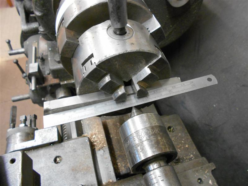
The drawing shows that there are two circular
rows of rivets at the rear of the smokebox and one row at the front, all
with a spacing of 5/16". Since my smokebox is 6.562" diameter that means
there should be 6.562 x 3.14159 / 0.3125 = 65.97 rivets, so sixty six rivets
in each row. Although I have a rotary table this is a particularly poor
choice of tool here because angular displacement is 5.45 degrees recurring.
I don't have a dividing head but a quick check of my lathe changewheels
found that a 66-tooth wheel is amongst them. Research on the internet reveals
that this particular size is commonly used in metric conversion from an
imperial leadscrew. First, how to hold the smokebox tube and I chose to
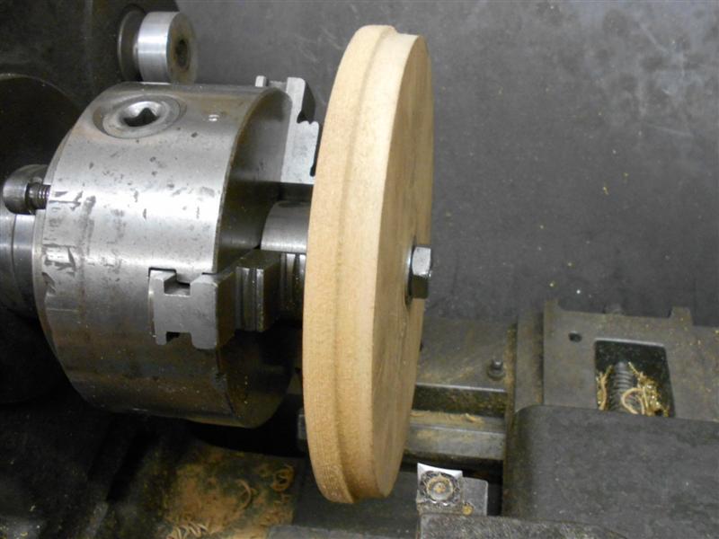
use MDF end-caps to fit in each end. Standing the tube on a piece of 20mm
thick MDF, I marked out the O/D for two pieces then cut them out, removing
the corners at the same time. Finding the centre of each piece, I drilled
a half-inch hole through in preparation for the next operation. Now I transferred
to the lathe and turned the O/D and a spigot to locate inside the tube.
|
 |
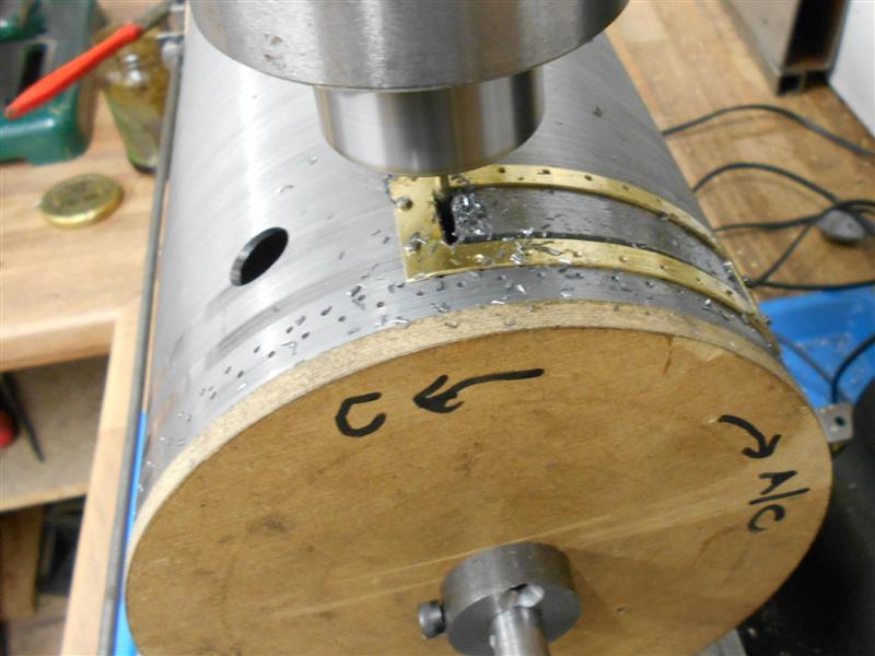
To hold the billets, I am re-using my wheel-turning mandrel
that I made for the tender wheels which has a half-inch diameter boss. Once
these were made, I found a length of 1/2" diameter mild steel rod which
I faced and chamfered at each end. This was a tight fit through the half-inch
holes in the MDF which was just what I needed. With the end-caps fitted
in and the rod through the middle, it was time to sort out the next stage.
The hole through the changewheel is 3/4" dia and I made a sleeve to fit
this to the 1/2" shaft, along with drilling a couple of holes in the changewheel
to enable the fixing of it to the MDF with woodscrews. |
 |
 |
Once I had this built up I started on the mounting and
for this I made a base out of 20mm MDF with a pair of risers from 2" x 2"
timber and a pair of 2" x 2" feet to clear the base of the drill. A half-inch
hole was drilled and reamed through a piece of 2" MS box-section tube and
then cut up to make a pair of pivots. All these parts were then assembled
and then I turned my attention to making some sort of indexing arrangement.
I opted for a spring-loaded detent and this was made from a piece of 1"
square MS box section for the carrier and 1/4" dia MS rod for the pin. The
end was linished like a screwdriver blade until it was a good fit in the
changewheel, then cross-drilled 1/16" for a spring retainer pin. . |
 |
 |
A suitable spring was found in the "come in useful one
day" drawer and a knob made to fit the other end of the detent pin. Also
made was a spring arrangement to apply pressure to the opposite end to keep
the linear position stable. After marking a few positions on the indexing
end and setting to the 180 degree position, I set the scribed line on the
smokebox to the centreline of the fixture. The table was taken off from
the drill and the machine screwed to the bench with plenty of clearance
either side. The fixture was placed over the base of the drill, the position
of the first hole found using a point in the drill chuck and then clamped
to the bench. |
 |
 |
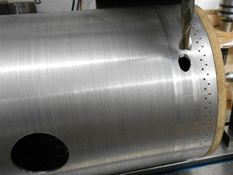
The first hole was centre-drilled and drilled, and a rivet
inserted to keep everything registered. Then I went round the smokebox using
just the centre drill, then round again with a 1/16" drill to complete the
first row of holes. A similar procedure was adopted for the other end although
the offset for the second row was set by eye, moving the fixture in a little
and along by 5/32". The slight deviation from true centreline makes no difference
at this diameter. This fixture was cobbled together in just a couple of
hours and the drilling of the 198 holes took about twenty minutes. I could
have done this job on the mill but I had something else set up on there
that I didn't want to disturb. That completes the rivet holes but I shall
leave the smokebox on the fixture and set it up on the mill for the other
holes; chimney, blast pipe, regulator etc. |
 |
| 4. Other Holes |
|
|
 |
After setting up my fixture on the mill to cut out the
larger smokebox holes it soon became obvious that, although satisfactory
for drilling, the setup was not rigid enough for boring. A few variations
of the setup were tried but the main problem was locking the work solid
in the rotational direction and finally a solution was found. Because the
jaws on the chuck wouldn't open wide enough to hold the 66-tooth wheel,
a smaller one was used instead. All subsequent operations were suited to
the rotary table, anyway. One of the jobs on my "to-do" list is to make
a tailstock to match the rotary table but, in the meantime, this cobbled
together arrangement works just as well. A lot of faffing around is needed,
though, so this job has moved further up the list. |
 |
 |
With the smokebox set at 180 degrees, the blastpipe hole
was drilled and then bored out to 7/8" diameter. No size is given but the
3/4" dia blastpipe connector needs to pass through and this should be enough
clearance. A lead washer under a collar acts as the seal. The saddle had
eight 6BA clearance holes made by opening up some of the existing 10BA holes
to 6BA clearance and these were then spotted through to the smokebox and
eight holes drilled and tapped to suit. The steam inlet holes have also
been put in. Rotating round to the 0 degrees position, the opening for the
chimney was drilled and bored to the finish size of 1.5/8" but the fixing
holes for the chimney were left for now. The two holes for the regulator
lever and the dummy whistle have to be created parallel to the horizontal
axis and the respective positions of these were calculated and made using
slot drills. |
 |
| 5. Regulator Cover |
|
|
 |
Because I'm following the drawing, rather than changing
the regulator arrangements, the slot above the regulator block needs to
be created to provide easy access to the valve plugs. The regulator cover,
as drawn, appears to be left for the model engineer to make as they see
fit and provides basic dimensions only. Two angular dimensions are given
and everything else can be worked out from this. First I cut some 20swg
brass sheet to size to create the base of the cover, adjusting the overall
length to suit my smokebox diameter. This was then clamped to some MDF and
the mounting holes drilled 10BA clear using co-ordinate drilling on the
mill. One of my general-purpose fixtures was set up on the mill and, using
the same co-ordinates, four 10BA holes were drilled and tapped to facilitate
mounting of the base for milling. Using a 1/8" slot drill the middle section
was removed, a clamp being introduced on the return leg to stop the waste
piece flapping around in the breeze. |
 |
 |
After deburring, the base was bent to fit the smokebox.
The smokebox was once again set up on the mill, the centreline found and
the two angular positions, 29 and 39 degrees respectively, scribed by dragging
a centre-point across the work. This allowed me to align the base in the
correct position and spot through the first of the holes which was subsequently
drilled and tapped 10BA. The base was then screwed to the smokebox and three
more holes drilled and tapped. After drilling four pilot holes, one in each
corner, a 1/8" slot drill was used to cut the regulator slot using the base
as the guide. I haven't used the rotary table a lot yet and have marked
the direction of rotation to match the winding handle so I don't inadvertently
wind the wrong way. At completion, the waste dropped away without problem
leaving the area ready for cleaning up. |
 |
 |
Attention now turned to finishing the regulator cover
and I chose to make mine as a three-piece fabrication. The neccessary sizes
for the upright section were calculated and transferred to a length of 16swg
brass sheet. The section was carefully cut out and the various bends put
in until I had a closed loop. The top was made from another piece of 16swg
brass sheet and cut to fit inside the loop. These two pieces were soldered
together and finally soldered to the base. There was much manipulating neccessary
here and I didn't take any interim pictures but my soldering is not pretty
anyway and better hidden from sight. I've done some filing and polishing
to get the basic shape but there is quite a lot more to be done. |
 |
| 6. Chimney |
Updated 24/07/20 |
|
 |
I have chosen to use the cast gunmetal chimney for my
project and, at first sight, it appears to be a reasonably good casting
without a lot of flash. The two halves of the core box have been aligned
quite well and the casting is symetrical. Because of the saddle shape of
the lower section, it is not the easiest casting to hold and I started by
getting it to run at true as I could in the 3-jaw and getting the bore to
size. However, I am going to deviate from the drawing in a small way later
and bored out to 1.500" instead of the given 1.625". Sorting out a way of
holding on the bore came next and I opted to weld up some more soft jaws
rather than make a mandrel. An expanding mandrel would be the ideal workholding
tool here but would be far more work than making the jaws, and a fixed mandrel
would have limited use. |
 |
 |
As you can see, my stick welding is on a par with my soldering
and should be hidden from view. A neat trick for locking the jaws in the
correct direction when skimming to size is to use a chain around the outside.
One of the hanging baskets is a little lop-sided at present but I'm hoping
she won't notice. I then ground up a piece of 3/8" square tool steel to
form an all-round 11/64" radius, which was done freehand on the grinder.
The work was loaded with a small amount of overhang at the front and the
top section formed first, skimming the O/D, facing the front and finishing
the upper curve with the same tool. |
 |
 |
I had slight movement just at the finish of the upper
curve so reversed the workpiece on the jaws to form the lower curve. I was
able to get further back and a better grip this way. To create the radius
for mounting to the smokebox, I set up my home-made lathe fixture on the
toolpost mount. I don't have a vertical slide so this does that job. The
lathe centre-height is already scribed on both sides of the block so it
only left a mounting boss and a couple of clamps to make. |
 |
 |
To cut the radius, I sharpened up a piece of 3/8" square
high speed steel as a left-hand tool and mounted it in the 4-jaw self-centering
chuck, itself mounted in the 3-jaw chuck. This was needed to get the neccessary
travel of the carriage. To set the tool, I used a rule against a live centre
to measure off the 3.9/32" distance required since plus or minus 1/32" is
going to make negligible difference at this radius. After checking to ensure
the tool would not foul the cross-slide at any point, multiple passes were
taken until I had a full clean-up and then extra passes to get to the required
11/16" height. I'm running at about 200 RPM and using a four-thou per rev
feed in the next picture. The live centre is being used purely as a safety
device - if I get a snag, this will prevent the 4-jaw chuck or tool flying
across the workshop. |
 |
 |
This is the component as machined so far and here it is
sitting on the smokebox. I now need to get the shaping of the outside correct
but because it is impossible to create compound curves with 2-axis tooling,
this will be done freehand with sanding drums in the dremmel and with files.
The bore will be modified later also, as mentioned at the start. |
 |
 |
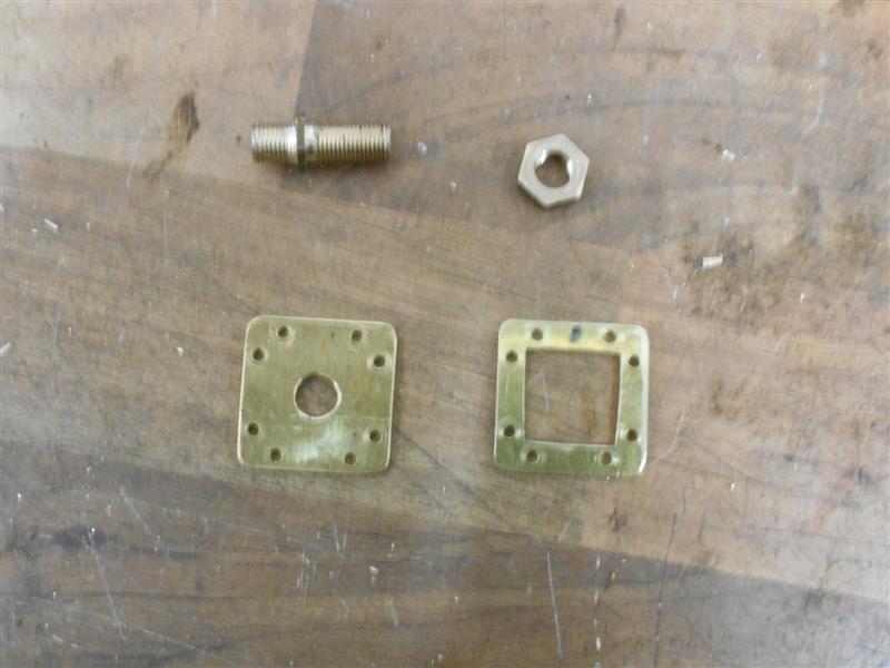
To fit the chimney to the smokebox, I made a simple drill jig from an
offcut of the boiler material and marked out the holes as shown. The outer
row of holes is at the diameter of the flange and is for visual alignment.
A 6mm hole for a clamp was also put in the centre and then the plate was
bent to shape, making sure the holes were in the correct orientation.
|
 |
 |
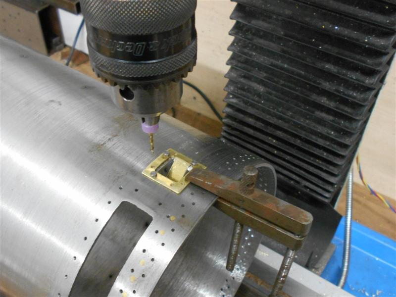
The holes were drilled freehand with one edge of the jig
resting on the vice jaw and the back packed to get the plate level at the
drill point, different heights being required for some of them. The jig
is free to float around a little. |
 |
 |
The chimney was then set on the smokebox with the liner
tube in place and the outer four holes spotted through. Because the four
closest to the centreline of the smokebox sit under the rim of the chimney,
I marked these with an angled scriber and centre-popped them. All the holes
were drilled as a generous 10BA clearance and 10BA threaded rivets (slotless
dome-head screws) used to fix the chimney in place. I filed a little off
the underside of the rivet heads to help them seat better on the angled
face of the chimney. |
 |
| 7. Regulator Stuffing Box |
|
|
 |
The regulator stuffing box is an awkward little thing
that sits on the side of the smokebox but not square to it. It needs a curved
mounting plate with the brass bush silver-soldered into it at an angle.
I started with some 16swg brass sheet which I milled to 7/8" wide for easy
mounting in a machine vice. The mounting holes were drilled next, remembering
to modify the formulae in the Zeus book to suit an elipse |
 |
 |
The bend was put in next and the work placed back in the
vice, attempting to match the angle that it sits at on the smokebox. The
hole for the bush was then machined using successively increasing sizes
of slot drill until final size was reached. The first end was sawn off and
then shaped, followed by a similar operation with the other end. I've been
using a reground cutter for the smokebox and plate holes, which is approx
0.550" so the bush was turned from some 5/8" dia bar to match. The drilling
and counter-boring were all done in the mill, however, and the tapping of
the 10BA holes using my little tapping fixture. I have not broken a single
tap since I made this fixture so it was well worth making. |
 |
 |
After checking that everything fitted together and sat
in the right place, the parts were silver-soldered together. Keeping them
held in the correct orientation proved to be a bit of a head-scratcher but
a solution was found in the end. I managed to fill one of the 10BA clearance
holes with silver solder but was able to drill it out freehand. |
 |
| 8. Smokebox Door |
|
|
 |
The drawing suggests making the smokebox door from the
casting, or spun from copper sheet but I am making mine from a slab of bronze
plate. Although I will attempt to get the exterior profile correct the inside
will be machined with the second operation in mind, leaving the door as
a slab with the inside recessed to enable holding on the 3-jaw chuck. This
is what I'm starting with. Lots of sawing, as one can see! The billet was
then loaded to the independant 4-jaw chuck and centred off. By setting the
turning tool close to the finish diameter I was able to check that there
would be enough material to get a full clean-up. |
 |
 |
The material was then faced of and the outside diameter
turned to 5.250". A 5/16" pilot hole was drilled through and then bored
to 3/8" diameter. The two-step recess was formed next, the first to 4.1/4"
dia x 1/8" deep and the second to 1.7/8" dia x 3/8" deep, the inner recess
being the one I will use to hold on for second op work. Finally, the O/D
was finish-turned to 5.125" dia and the 45 degree chamfer formed using the
compound slide. This ensures that the angle matches perfectly with the chamfer
on the smokebox door ring which was turned in similar fashion. Turning the
inside in this manner will also make it much easier to hold on the mill
when it comes to drilling hinge holes etc. |
| There are many ways to create the external
form of the smokebox door, CNC turning probably being the easiest. On a
manual lathe the main problem is how to move the cross-slide and saddle
together in a controlled manner to form the spherical external form. My
solution was to create two pivot points, one fixed to the bedway and one
to the cross-slide, joined by a steel bar with reamed holes spaced according
to the radius of the smokebox door. Scaling from the drawing, I measured
the height of the arc and the length of the chord which enabled me to calculate
the radius of the door using the standard formula. Working from three different
drawings it averaged out at 8.7/8" within a few thou. After checking that
the various parts would fit together correctly I started by drilling and
reaming a pair of 8mm holes 8.7/8" apart in some 24mm x 10mm flat black
bar and making a pivot pin from an 8mm Allen bolt. An extension piece for
the bedway clamp was also made from the same flat bar, and a pivot block
turned from some 20mm dia mild steel with an 8mm spigot on top. |
 |
 |
The pivot bar has to be parallel to the bedway when the
cutting tool is at centre so determining the correct location for the pivots
is reasonably important. The saddle moves towards the chuck when the tool
is at maximum diameter and allowance has to be made for that. In my case,
that meant leaving a 16mm gap between the bedway clamp and the saddle. The
right-hand photo shows one of the early cuts in progress and the angle of
the pivot bar can be clearly seen. I am using the cross-slide power feed
for this and taking ten thou depth of cut at each pass, set by adjusting
the compound slide. |
 |
 |
The next two photos were taken after the final pass, the
first one showing more clearly how the bedway clamp was attached and the
second showing the high-quality finish obtained with this setup. There has
been no polishing up to now and, probably, none will be needed. One useful
by-product of this method is that there is no need to back off the slide
each time to avoid reverse cutting. The backlash in the cross-slide leadscrew
automatically clears the tool from the face when winding back. |
 |
 |
Before removing from the chuck, a form tool was used to
create the 3/16" corner radius and a small amount of blending undertaken
with an abrasive block. The final shot shows the door sitting in the ring. |
 |
| 9. Door Clamping |
|
|
 |
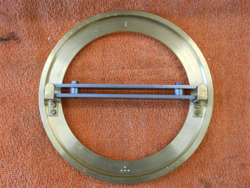
A pair of brackets were made to support the door locking
bars and have been screwed to the inner face of the door ring. The bars
are 1/2" x 1/8" mild steel cut to legth and joined with a pair of 2BA screws
and a 7/32" spacer between. The door locking screw is made from 5/8" diameter
stainless bar, the front being threaded 4BA and the shank turned to 3/16"
diameter then parted off to length. Two flats were milled on using the 4th
axis chuck on the rotary table, and the front lamp bracket was milled from
solid in a similar fashion using the adjustable support at the front. The
boss in the centre of the door was turned from 1/2" dia brass, threaded
3/8" x 32tpi and a nut made to suit. |
 |
| 10. Door Hinges |
|
|
 |
To make the smokebox hinges, I have silver soldered a
pair of 1/8" brass flats to a piece of 3/8" diameter brass rod
with a section milled away. These were then milled to size all round and
the hinge pin holes drilled 5/32" diameter. They are quite small and difficult
to hold for subsequent operations but I set up two angle plates to create
a raised table and clamped a fence along it to rest the workpiece against.
The bars were then reduced in width to 7/32". |
 |
 |
I made a new set of soft jaws for my small milling vice
and milling shoulders onto the jaws at 0.080" deep by about 0.030" steps
each side and a stop-point two-thirds of the way along. The hinges were
then dropped in and the four holes produced using co-ordinate drilling.
the middle part of the hinge was removed during the same setup. The hinge
bosses were made by turning some 1/2" diameter brass down to 0.142" and
threading 4BA for half the length. The bar was then transferred to the mill
and the four sides milled followed by drilling the hinge-pin hole. Then
it was back to the lathe and part off. |
 |
 |
Finally, a 4mm reamer was passed through each of the
holes, the radius linished onto the hinge bosses and a 4mm rod passed through
to check that each hinge worked correctly. During a trial assembly I found
that, at ninety thou thick, the arms were too rigid to bend so subesequently
thinned them to 1/16" thick. The hinge boss holes were drilled in the
smokebox ring, the bosses fixed and the door clamped to the ring. The fixing
holes were then spotted through and the parts riveted together with 1/16"
countersunk brass rivets. |
 |
| 11. Door handles |
|
|
 |
The two handles for the smokebox door lock were made from
mild steel, the tapered section being made by step-turning the diameter
and filing to shape in the lathe with an old gash file kept for the purpose.
The 6BA thread was then cut, and the head formed by parting though half-way
and filing the radii on the edges before parting through. |
 |
 |
The two bosses were simple turnings from 3/8" diameter
mild steel bar but the front handle needed to have a hole drilled and tapped
at eighteen degrees and this was made in the tilt and swivel vice. This
was spot-faced with a 1/8" slot drill prior to drilling. To make the square
hole in the rear boss, a 5/32" drilled hole was broached in the vice with
the end of a broken M5 tap, the square part of the shank being 4mm. I hate
filing and this is a quick and dirty way of getting a cheap broach since
the shank is also HSS, unlike drills which can often have a soft shank.
The door bolt was finished off by milling the flats to suit. |
 |
| 12. Dummy Whistle |
|
|
 |
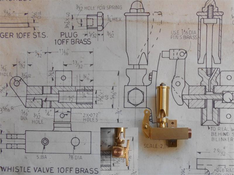
The whistle on the side of the smokebox is ornamental
only, with the real whistle hidden elsewhere, but the valve is designed
to work and pass steam to the real whistle. Between the frames seems to
be favourite and this will be looked at later. The drawing shows various
small parts, all drawn at 2:1 scale and although the bell is a reasonable
representation of the original, the rest is not, even going so far as to
be mounted back to front. At this stage, I'm just working to the drawing
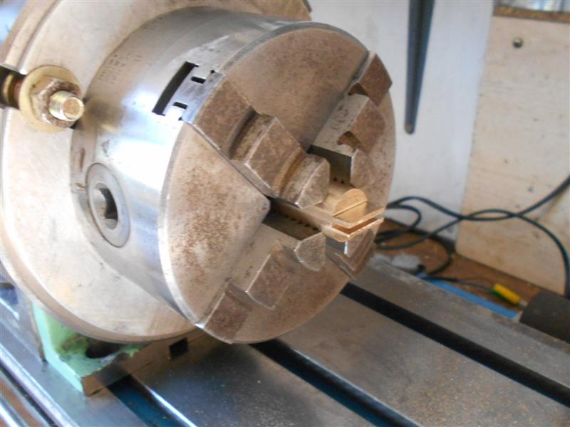
and started by making the whistle valve. This is drawn as a square body
with pair of pivot arms projecting upwards at the rear to support the operating
lever. I decided that it would be easier to machine the whole thing from
solid rather than try and silver solder something on at the back. A piece
of 5/8" diameter brass bar was loaded to the 3-jaw chuck, faced and skimmed,
and the 1/16", 3/32" and 5/32" dia holes drilled to their respective depths.
To get the flat bottom for the valve seat, a 4mm slot drill was used. |
 |
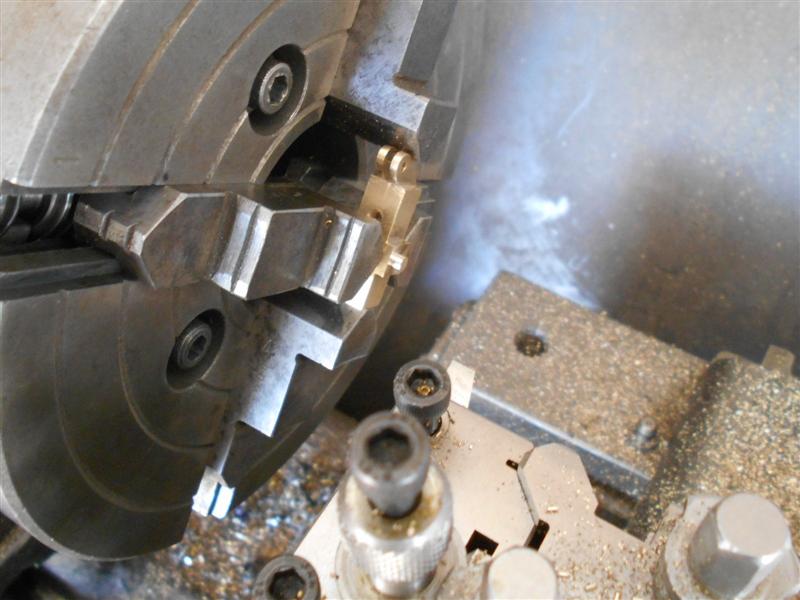
The component was parted off and, over on the mill, was
loaded to the vertically-mounted rotary table and the slot cut with a 1/16"
slitting saw, followed by milling the two sides away to leave the pivot
arms. Next it was squared up in the vice and the base milled to size, this
acting as the reference face for subsequent operations. The various faces
were then milled to size, finishing with the rear face. A 1/8" high upstand
was left on the this to allow for a spigot to fix the mounting plate to.
|
 |
 |
Last jobs on the mill were to drill and tap the cross-holes,
and to shape the pivot arms. Then it was back to the lathe and turn a 1/8"
diameter spigot onto the mounting boss. The work is only really clamped
on two jaws gripping the sides, the lower jaw being used to adjust the position
and the upper end just lightly resting against the pivot arms. |
 |
 |
The mounting plate was made from some 1/16" x 1/4" brass
strip and a 1/8" diameter hole made to accomodate the whistle spigot plus
two mounting holes. To make the slight bend needed to fit the smokebox outer
diameter, the part was placed on one of the lathe chuck hard jaws and the
part given a thump with a suitable former. For something so small, I really
can't be bothered about trying to get the radius exact! The two parts were
later soldered together. The whistle bell was made from 3/8" diameter brass,
pilot-drilling the bore first, then turning the O/D and finishing the bore
with a small boring bar. The wall thickness makes it a fairly delicate piece
so care was taken, and the feather edge was made by swinging the coumpound
slide to thirty degrees. Trying to plunge with a chamfer tool could well
have ended in disaster. |
 |
| Before parting off the part, still on the stock bar, was
taken to the mill and the three cutaways machined using a 1/8" diameter
slot drill. After a little hand-work with a file to create the correct shape,
it was returned to the lathe and parted off to length. The base of the whistle
was turned from the same stock, the operating lever from some 1/16" brass
sheet, and the bell spindle from 3/16" diameter brass rod, all simple machining
operations. I haven't put the 1/32" diameter hole in the base and probably
wont. A tiny hole in the side of the valve would allow some steam to escape
to mimic operation when the whistle is used. When it came to making the
spindle, I discovered that the draughtsman had made yet another mistake
on the drawing and the bell is 1/8" too long. Since I'd already made and
scrapped one bell before, I decided to lengthen the spindle instead. I may
remake these parts later and will probably round off the edges of the valve
as it's too angular and looks nothing like the real one. |
 |
| 13. Steam Pipe |
|
|
 |
Although the drawing calls for 7/16" dia x 18 swg copper
tube for the steam pipes, I had a short length of 12mm x 1mm wall tube in
stock and have used that instead. I have also beefed up the flange to the
cylinder from 1/8" thick to 3/16". I started by milling up a pair of rectangles
from 3/16" brass plate, then drilled the two bolt holes 4BA clear. For the
steam pipe hole I first drilled through at 10mm dia followed by a 12mm slot
drill to a depth of 1/8". The tube was parted off to length and polished
down to be an easy fit in the flange. They were then silver-soldered together
and, because the tube was nicely annealed from the silver-soldering, I put
the bends in using a convenient spring and an M10 bolt that happened to
fit nicely together. |
 |
 |
The bending distorted one of the tubes at the mouth but
I was able to get it circular again by pulling it up tight in a 12mm mill
collet. A 9/16" dia filing button was made and the shape of the flange finished
freehand on the linisher using the button as a guide. Here is the first
one bolted to the cylinders. |
 |
 |
I've used M14 x 1 rather than 9/16" x 26tpi for the top
section of the steam pipes and started by making the nuts. They should be
made from 19mm or 3/4" AF hexagon but, not having any, I made them from
7/8" dia round bar instead. I drilled and tapped deep enough to get five
nuts from the bar and then moved over to the mill to create the hexagon.
I couldn't be bothered to set up the rotary table, nor did I have any larger
hex bar to make a holder, so used a thirty degree plate to set the angles
instead. After doing three sides, I used a different way to set the intermediate
angle, then continued as before. This is not super-accurate but it doesn't
need to be, just close enough to fit the spanner. |
 |
 |
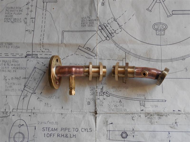
Then it was back to the lathe to chamfer and part off
each nut. The threaded sleeves were made next, using the nuts as a gauge,
and with a spigot bored in one end. This was made to be an easy fit over
the steam pipe. The clack bodies were made earlier (no pictures) and the
steam pipes had a hole put in the side to set the clack bodies into. The
whole lot were then silver-soldered together, cleaned up and the threads
run down again. The one on the right is a little distorted near the base
due to having to tweak the angle a bit, but it's never going to be seen
once assembled so not worth trying to do anything about. |
 |
| 14. Whistle Steam Feed |
|
|
 |
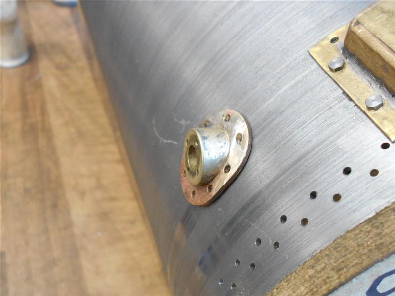
I had originally made the plate and union for the whistle
steam feed but found it difficult to assemble. It also looked nothing like
the prototype so I decided to try and make something better. After a couple
of false starts (things went pear-shaped) I finally settled on two plates,
one inside and one outside the smokebox bolted together and a union fitting
mounted on the inner plate. I started by cutting two squares from some 20
swg gauge brass sheet and milling them to 0.900". After setting the centre,
1.8mm dia holes were then drilled through at the 0.359" / 0.281" positions
in both plates and 1/4" dia holes at the centre. The outer plate then had
this hole opened up to 7/16" and finished square with a file at 0.562".
After bending, this plate was clamped to the smokebox below the regulator
coverplate and the holes spotted through. |
 |
 |
After the outer plate was fixed with 10BA screws, the
square shape was filed in the smokebox to match. A simple union was made
from 5/16" hexagon brass, drilled 3/32 and threaded 1/4" x 40tpi to accept
1/8" dia tube, this being fixed to the inner plate with a fibre washer to
take up the curve of the smokebox wall. There is a little more filing still
to be done, and red hermatite equivalent will be used to seal everything
on final assembly. It's still not exactly as prototype but certainly better
than what was on the drawing. |
 |
| 15. Boiler Ring |
|
|
 |
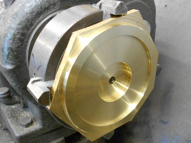
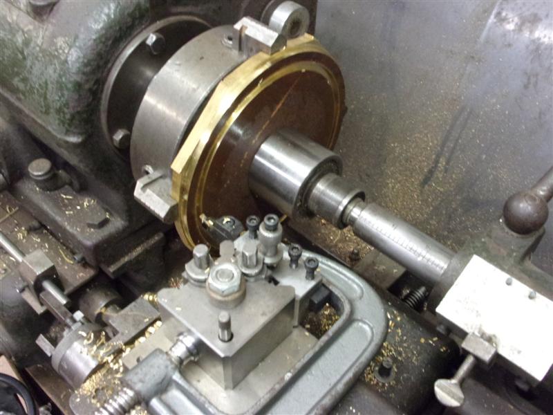
I have made a start on the ring that connects the boiler
to the smokebox using another section from the bronze plate. I had previously
prepared the rough blank using a jigsaw with a fine-tooth HSS blade. The
blank was loaded to the independant 4-jaw chuck because this is the only
chuck I have that is large enough. The O/D was turned first, then the centre
trepanned out using a grooving tool mounted side-on. The clamp is there
to help protect the toolpost. If the tool snagged, it is possible to break
the pull-in clamp or the back of the toolholder. The bearing is there to
extend the live centre. When trepanning, I prefer to take small pecks at
two different diameters so the the groove is about thirty thou wider than
the tool. This way, the swarf never jams up in the groove, which becomes
more important the deeper the groove gets. Here, I'm nearly at breakthrough
with a full witness showing on the back. |
 |
 |
At this point I stopped and removed the part from the
chuck, not wanting to machine my chuck jaws. A few smart blows with a hammer
and the centre fell away and will be used for something else later. The
next picture is a close-up of the tool I used, a parting / grooving tool
with 3mm carbide tip. I've ground away the bottom of the tool on the one
side to ensure it doesn't rub on the work. |
 |
 |
Then it was back into the chuck with the jaws reversed
and holding on the inside. The ring was then turned to about twenty thou
oversize and the front faced for a full clean-up. Because I don't have a
proper faceplate for this lathe I held it as loose as I dare on the O/D
and turned the diameters with very gentle cuts. The first operation was
face, turn the smaller O/D to forty five thou below the smokebox diameter
for the cladding and bore to suit the O/D of the boiler. I had to use 3mm
packers to bring the ring forward enough to machine the O/D which were,
obviously, removed before starting the lathe. |
 |
 |
Second op was to hold in the previously turned bore and
turn the O/D to the bore diameter of the smokebox, looking for a snug fit.
The front of the boiler barrel was a little out-of-round after all the work
of late so had to be gently tapped to shape until it fitted firmly to the
ring. This will be held in place by four countersunk screws and will be
covered by the cleading. |
 |
| 16. Next Item... |
|
|
| |
|
|