| Drawing 17 - Cab Fittings, Clothing
|
| 1. False Backhead |
|
|
 |
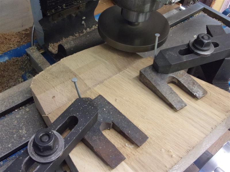
I have made the former for the backhead cladding in a
similar fashion to the other firebox formers, using an offcut of 40mm solid
oak kitchen worktop. The backplate is not flat, there being a fifteen degree
change of angle about in line with the lower water level bushes and a return
change near the bottom. After cutting out the basic shape with a jigsaw,
I mounted the former on the mill table and set up to flycut the first angle.
The nails are to prevent the wedges wandering downhill due to the slope.
I have set the plate at ten degrees for this cut as it is the shortest distance
and will leave the greatest thickness of material. The flycutter is a home-made
affair with a boring bar in it. |
 |
 |
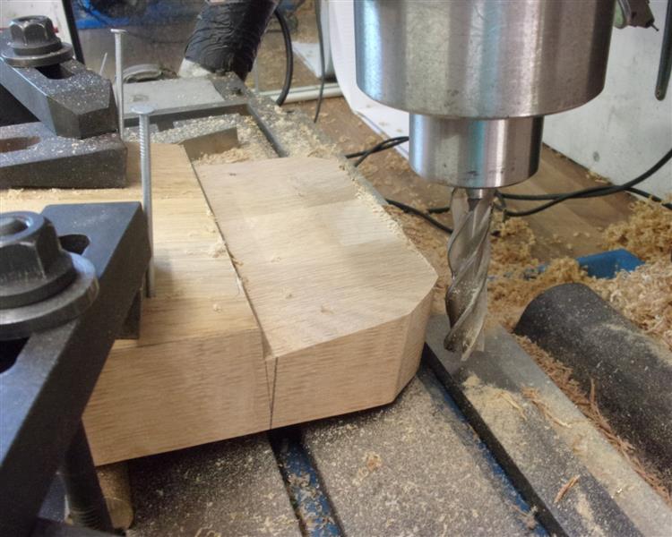
This is the first section finished. Each depth of cut
was 100 thou, four passes being needed to clean the top section. The small
boring bar has one of the very sharp, polished carboide tips loaded. I needed
the top to be square to the newly-created face and this was milled with
a long-series 5/8" dia end mill, finishing at 2.15/16" from the bend line.
A quarter-inch allowance had been left on the height specifically for this. |
 |
 |
Then the work was set up at five degrees in the other
direction to get the planned fifteen degree face. This one was more of a
challenge to set up because the clamps have to be between the two bearing
points of the former. To stop the workpiece rolling away, a cheap, rubbish
square was clamped down to act as a fence where it overhung the edge of
the table. The final setup was to create the 3/4" wide section at the bottom
and for this the former was clamped flat to the table and the tool height
set to just kiss the scribed line. |
 |
 |
The backhead former has now been shaped and had the radii
filed on. I tried to use the linisher but my belts aren't coarse enough
and I was scorching the wood. The former was laid onto a sheet of 20 swg
brass and the basic shape marked out with 3/4" allowance on each side for
the returns. A fifteen degree fold was put into the workpiece and this was
then clamped to the former and flanging began. |
 |
 |
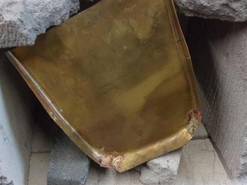
I annealed the material about four times and the next
photo was taken after the second annealing. Because of the fairly tight
bends at the top, the material was creasing quite considerably. After the
fourth annealing, it became obvious that I would not be able to eliminate
the creases. Unlike the copper for the boiler where the material was able
to fatten up and flow, the thinness of the brass meant it was easier for
it to deform rather than flow. Therefore, a pair of triangular sections
were removed at each corner and the material beaten over in separate sections.
These were then silver-soldered together prior to further melding. |
 |
 |
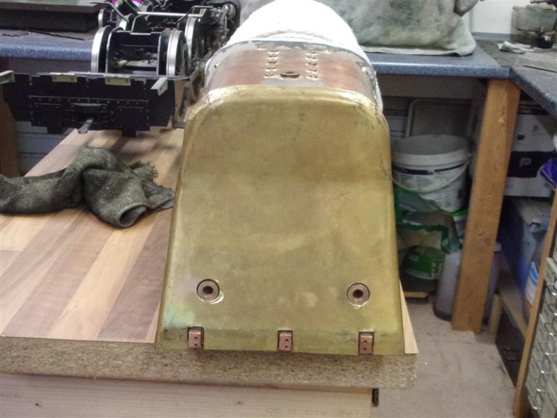
Once the final shape had been achieved, the flanges were
trimmed back to about 5/8". Then the backhead was offered up and the height
set with packing. The bar across the top is to check that the top is about
level with the bush for the steam manifold. Then it was just a case of marking
out the various cut-outs for the boiler bushes, the firehole and the platform
support blocks. |
 |
 |
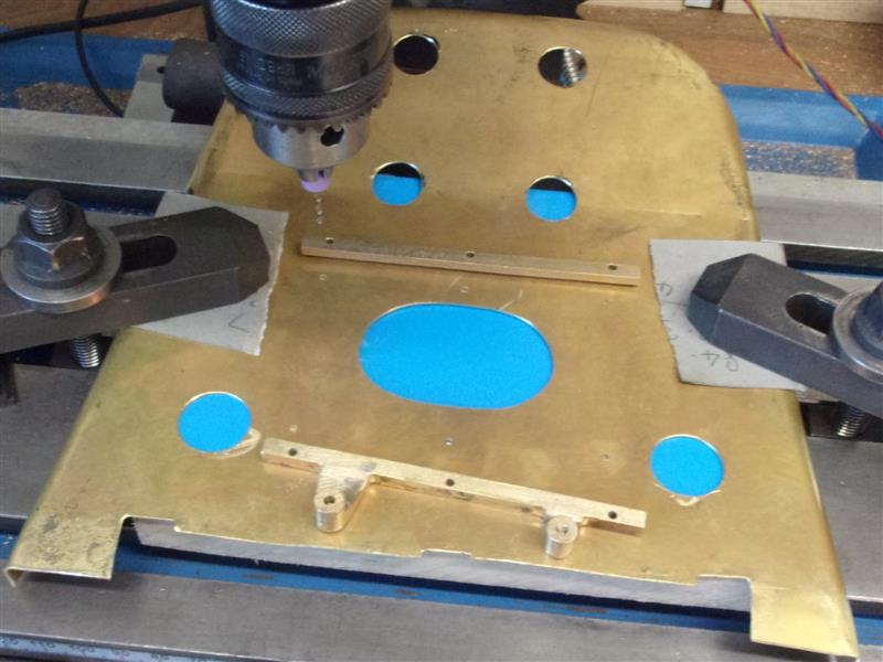
I marked the position of the gauge glasses by blue-ing
the bush faces and offering the plate up. After drilling the four holes
at 1/4", I checked the position of them and eased them to the correct positions
with a rat-tail file. Then a step drill was used to open them up to the
nearest clearance size. Next, I made up some spacers and washers to hold
the backhead in the correct place using the blanking plugs I'd kept from
the pressure test. I was then able to mark out the firehole from inside
the firebox. This was set up on the mill to remove the waste. |
 |
 |
Who needs CNC? CHC will do. Careful hand control enabled
me to cut the waste out freehand using a 1/8" slot drill. The slot on the
side is where my blower pipe comes out and should be almost invisible when
the cab is built. As can be seen, the workpiece is clamped down onto a piece
of timber and everything done by eye. Quicker than chain-drilling is one
is careful. |
 |
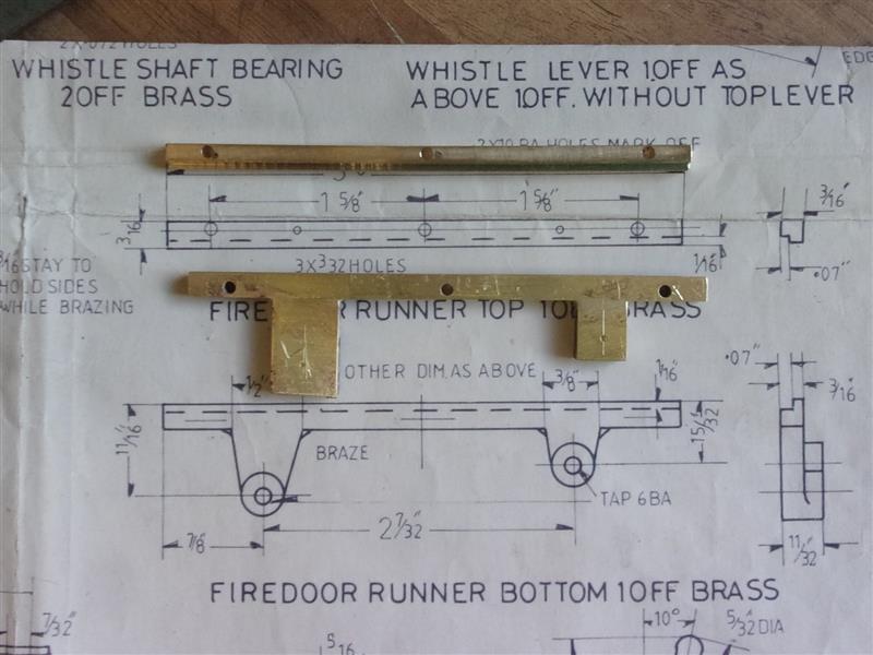
| 2. Firehole Door Rails |
|
|
 |
The backhead was replaced on the loco and the firehole
dressed with files. Attention then turned to the firedoors and rails which
are made from 3/16" square brass. These were cleaned up, followed by milling
the door channel and drilling the mounting holes. For the lower rail, a
pair of bosses from 3/16" plate were silver-soldered on and the holes for
the bushes marked out. A pair of bosses with 3/16" dia spigots were also
made up and these were soldered into 3/16" dia drilled holes. This provides
a little mechanical strength as well, although I expect it's not needed.
Ive also cut the material for the firehole doors from 16 swg brass sheet
but I'm making these an 1/8" shorter than specified on the drawing because
the oversize gauge glass assemblies would otherwise make it a bit cramped-looking. |
 |
| 3. Firehole Doors |
|
|
 |
The firehole doors are more than just flat plates, they
have some sort of baffle on the front. A piece of 16 swg brass was bent
around a 5/8" diameter bar and two firedoor fronts cut from it. The sides
were marked out by tracing from the drawing, then cut and linished to shape.
As noted on the drawing, a spacer was used to help hold things together
during silver-soldering. I made a pair of 3/16" dia rods drilled and tapped
8BA each end, then drilled 8BA clearance holes in the sides, a pair together
each time. The small drilling fixture was particularly good for this. |
 |
 |
The rods held the side nice and square and also acted
as a clamping point. 1mm silver solder was laid inside against the corners
and heat applied from below. Between the screws of the clamp the second
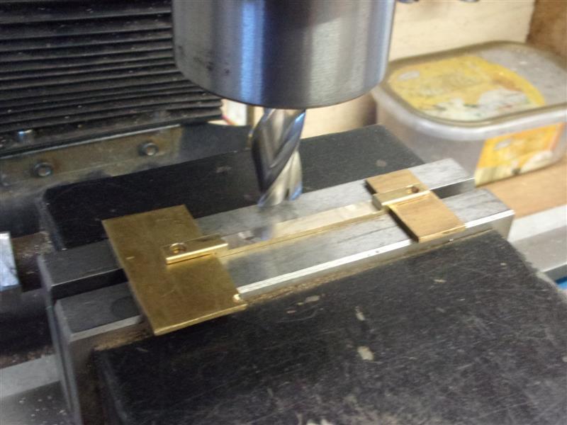
one can be seen waiting to be soldered. The bottom was milled top size next;
I removed the screws but left the spacer in place for rigidity. I scribed
a line at 1.9/16" and set this, by eye, level with the vice jaw. Exact size
is unimportant. |
 |
 |
To solder the two parts of the door together, I put the
screws back, just in case the second heat-up softened the earlier work,
and made a horseshoe of silver solder to rest around the baffle. Heat was
applied from below until the solder melted and flowed into the joint. One
hand for the torch and one for the camera here. Last operation on the doors
was to add the bosses for the operating levers. I made up a pair of 5/16"
dia brass bosses that went right through to the door plate and step-milled
holes to suit. This makes the boss stand vertical to the back face and saves
having to make an angled face on the bosses. They can be soldered on the
inside, too. |
 |
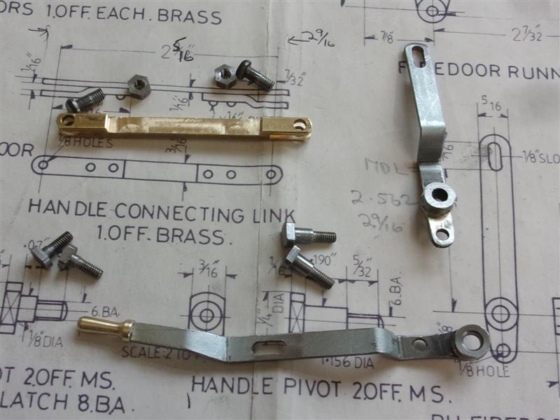
| 4. Firedoor Handles |
|
|
 |
Before making the firehole door handles, I fixed the rails
to the backhead so that I could check all the hole positions. The backhead
was clamped onto a lump of 20mm MDF and the six 8BA holes drilled and tapped.
The handles were cut from 16 swg mild steel sheet, then bent at the appropriate
positions. The pivot bosses, as drawn, are on the wrong side of the handles.
I silver-soldered mine on the outside, the bosses having a 3/16" diameter
locating spigot. The slots for the door pins were done after bending. |
 |
 |
The drawing shows the linking bar as a fabrication of
three pieces but I made mine from 3/16" square brass bar and, after facing
to length, drilled the two holes for the cotter pins. Then I milled the
two slots using a 65 thou slitting saw. Then I milled away the top of the
centre section to more closely resemble the prototype. I put some 1/16"
packing pieces in the slots and dropped the bar into the vice. I'm only
holding on 1/16" but it's enough for this. |
 |
 |
To make the clevis pins, I used 1/8" diameter iron rivets,
holding them in a collet and threading them 5BA. Because there is practically
no head to hold on, I loaded them into a block with a 1/8" drilled hole
through it, then offered it up to the collet. That's good enough to set
them square and run a button die down. |
 |
 |
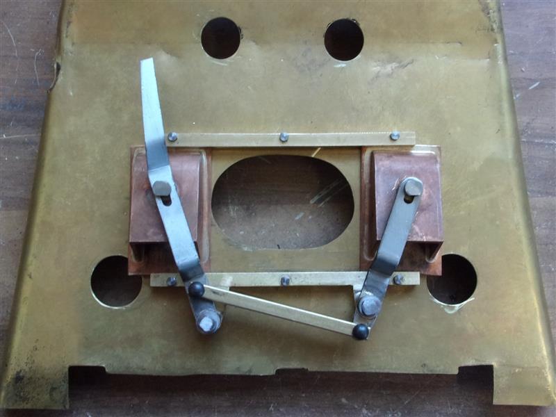
After making the pivot pins, I assembled everything to
check it all worked as it should. However, I didn't like the look of the
handles, I felt they appeared too wide and clumsy. I decided to thin them
down to 1/4" wide and also dress the heads of the clevis pins. I also made
the brass top for the handle, which is soldered into place, and the door
latch. |
 |
| 5. Dummy Gauges |
|
|
 |
There are five dummy gauges to be made from brass bar.
These were made in a single operation, drilling and boring the minor diameter
through for either two or three parts per size, then boring the othr inside
diameter for a depth of 5/32". The o/d's were skimmed and the smaller diameter
turned behind with the parting tool. The brackets for the gauges have also
been made from 20 swg brass offcuts, hacksaw and files being the main tools
of the day. This one carries the main pressure gauge with the dummy steam
heat gauge above. |
 |
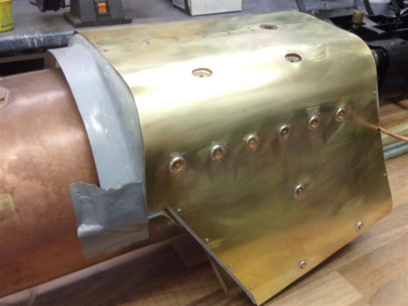
| 6. Front Throat Cover |
|
|
| I have made the front throat cover as three
sections because it was easier to adjust for a good fit and because none
of the joins can be seen when the loco is assembled. The material is 1mm
galvanised steel with the galv dissolved off in the pickle tank. A 1/8"
joiner at the bottom acts as a packing strip to space it forward to the
correct distance and a single screw (not in this picture) into the foundation
ring holds the assembly in place. The top will be held by two grub screws
in the barrel ring: the two screws at the 4 and 8 o'clock positions are
temporary. This needed quite a lot of fiddling around to get a nice fit
at the sides and barrel. |
 |
| 7. Firebox Cleading |
|
|
 |
The cleading for the firebox was cut from 24 swg brass
sheet after first making up the sides in cardboard. To keep things manageable,
I went for a join in the middle using a couple of pieces of 14 swg brass
for joining strips. I started using 12 BA screws to fix the cleading but
stripped a couple of threads. I then discovered that my small-head 10 BA
screws were made from the same hexagon-size as the 12 BA screws so opened
all the holes out to the new larger size. Having it in two halves also made
it easier to mark out the position of the steam manifold and much simpler
to put the bends in using the club's bending rolls. I will put a few more
screws in later but they wont be trying to represent the spacings of the
prototype. |
 |
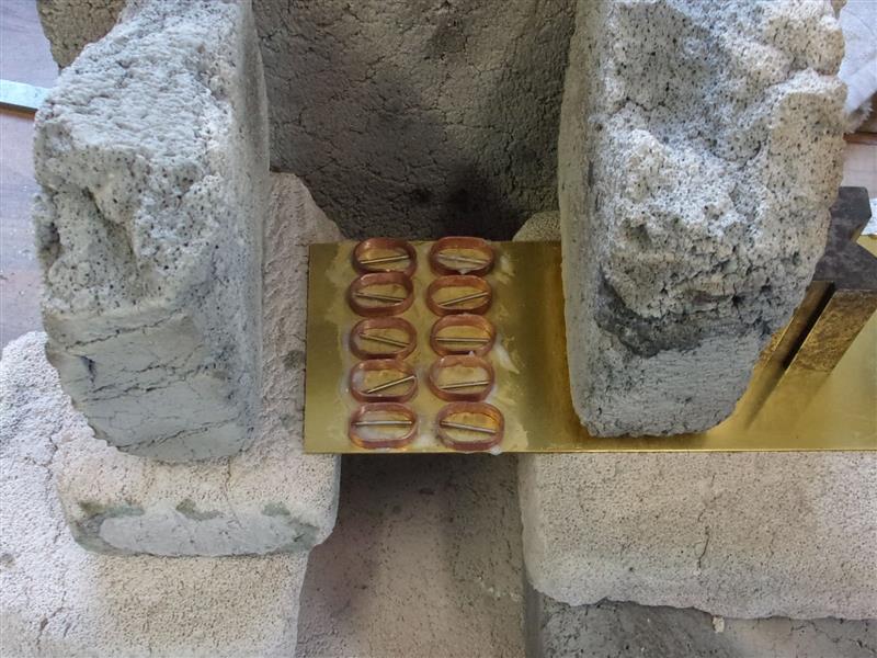
| 8. Dummy Mud Rings |
|
|
 |
There are four mud rings on the top of the firebox and
two near the front of the boiler barrel. To make these, I started by parting
off a load of 15mm copper tube into 5mm long rings. These were then squashed
in the vice to form the oval shape and reformed at each end around 3/8"
dia bar. A piece of 20 swg brass sheet was coated in flux, the rings rested
on top and a piece of silver solder rested inside each ring. Heat was applied
from below the sheet until all the solder had melted. It naturally flows
to the edges of the ovals and penetrates underneath. The picture shows the
assembly a minute or so after the heat was removed. |
 |
 |
Each of the mud rings was then cut from the sheet with
a junior hacksaw and the edges linished. Meanwhile, a start was made on
the mud hole bridges, with a pair of 2mm channels being milled into a length
of 1/2" x 1/4" brass bar. The outer wall thickness is about seventy five
thou. To make each bridge the end of the bar was first cleaned up in the
lathe followed by drilling the bolt hole on the mill. These were then cut
off with a hacksaw and put to one side. |
 |
 |
Once they were all finished, they were set in the milling
vice and finished to 3/16" thick. Then they were loaded back to the vice
and the legs formed by milling away the outsides as shown. This method allowed
them to be upended and the other side done at the same settings, leaving
the legs 1/16" thick. I kept the cutter at the finished depth and milled
with the side of the cutter, 25 thou per pass. Back with the soldered parts,
an 8BA hole was drilled and tapped in the centre of each dummy mud ring
and a bridge screwed to each. I haven't bothered to completely clean up
the outside of these because they are never seen once they are soldered
into the cleading. |
 |
| 9. Dummy Washout Plugs |
|
|
 |
Because I decided to do away with the square-ended stays
at the top of the firebox, I needed twenty-one dummy washout plugs and I
have made these from 1/2" dia brass bar. First operation was to turn the
two outside diameters, drill a 6BA tapping holwe and part of to length.
I have made mine a little shorter than drawing to reduce the chance of fouling
on the cross-stays, with 5/32" under the head and a 1/32" thick flange.
For the second operation, I changed over to an ER25 collet and plunged the
bore with a small HSS tool. Because one cannot control the depth with collets
like this (except with a backstop bar), after tightening I touched the tool
on and wound the compound eighty thou to set the depth. |
 |
 |
The square plugs were made from 1/8" square brass, held
in another ER25 collet. Because it is an eight-segment collet, it held perfectly
well in the 3mm-4mm dia one. They were turned to 110" diameter by 3/32"
long and threaded 6BA then parted off with the square section finishing
at 0.105" long. These were then screwed into the plugs and pulled tight,
followed by linishing the backs flat. The one at the bottom is finished.
The holes were marked out on the cleading and drilled next, using a stepped
hole drill to make the 3/8" dia holes. A length of 4" x 2" was clamped to
the table and a 1/2" hole drilled quite deep. The sides were then rested
on the timber and the holes drilled freehand. It is worth mentioning that
these type of cutters cannot grab because of their geometry and also that
the top of the cleading acts as it's own fence, resting against the side
of the timber. |
 |
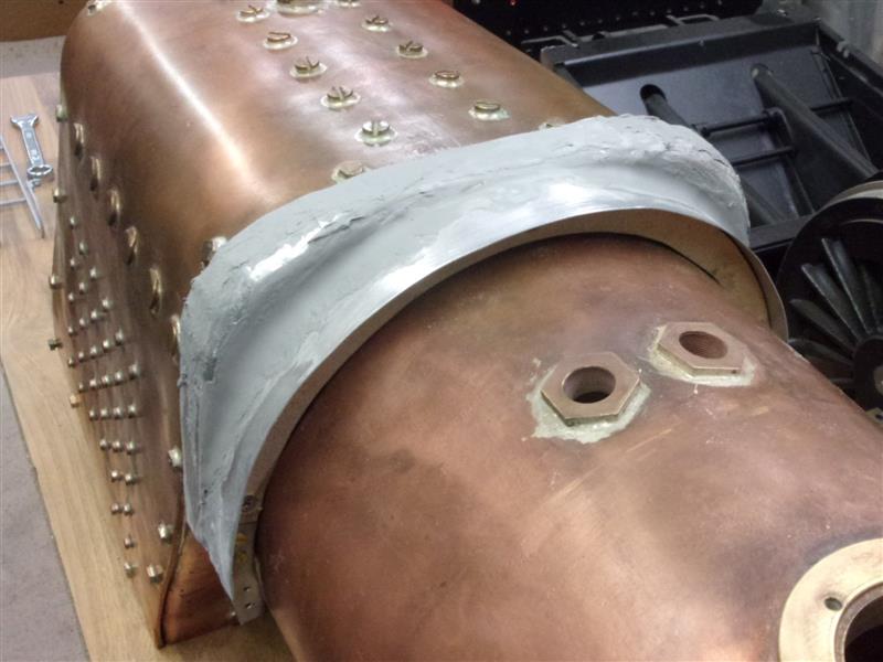
 |
I drilled and shaped the mudrings at the same time and
then soldered these to the cleading, setting them about 1/8" below the surface.
I've rested a horseshoe of solder on each one prior to heating. The dummy
washout plugs were soldered in next, remembering that there are six high-level
ones on the driver's side and only five on the fireman's side, offset a
little forward of the others. This is what they look like on the driver's
side although I have not put the mudhole door handles back in yet. |
 |
| 10. Boiler Cleading |
|
|
 |
To make the saddle that sits atop the boiler, I cut some
20mm MDF to shape with a jigsaw amd folded some aluminium sheet around it
to form a rough curve. Then another piece was cut and screwed to the front
to support the barrel cleading. I also made a section for underneath but
realised that this was not going to work because the cleading needed to
be tight up against the boiler strap on the underside to get the boiler
sitting correctly. The piece on the right was discarded. |
 |
 |
Car body filler was liberally applied and left to set.
After sanding down, the process was repeated a couple more times until a
reasonable shape was formed. Cardboard engineering was used to get the basic
shape of the boiler wrapper and the shape transferred to a sheet of 24swg
brass. It was cut out using a diamond disc in the Dremel; I found this easiest
as I have very few sheet metal-working tools. |
 |
 |
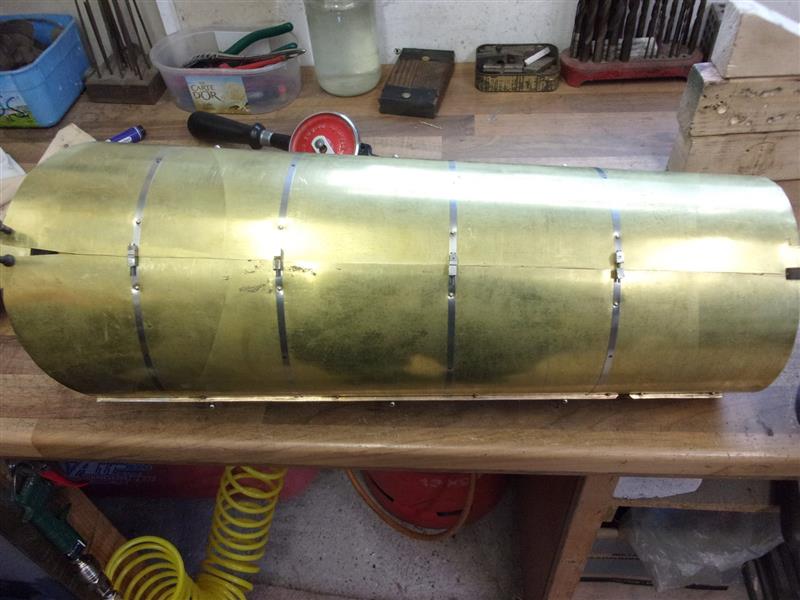
I borrowed the bending rolls from the club to form the
barrel shape, then trimmed it to fit and made all the holes for the dome,
safety valves and injector clacks. I also drilled the holes for the washout
plugs and the mudhole doors and soldered these items into position. Boiler
bands were made from 3/16" wide stainless steel ties used by the air
conditioning trades with 8BA fixings attached. Once positioned, they were
drilled and fixed to the wrapper with 1/16" brass rivets. |
 |
 |
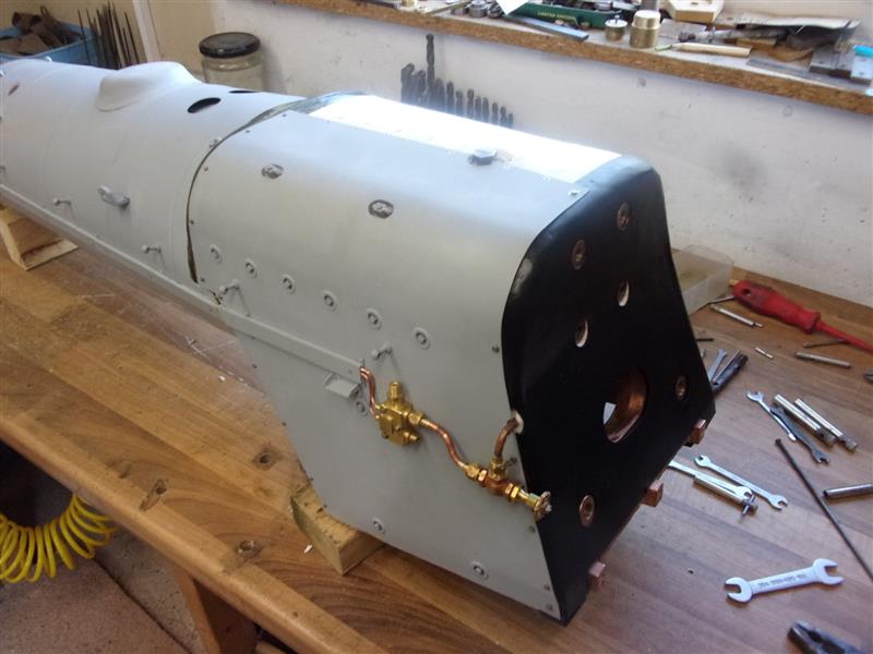
I had previously forgotten to silver-solder the regulator
bracket to the boiler and didn't want to heat it all up again. I, therefore,
made a more substantial one-piece bracket which Ifixed to the wrapper with
8BA c/sunk screws and soft-soldered (high temp stuff) for good measure.
I also made up the dummy pipe cover that adorns the driver's side, making
small recesses to clear the boiler bands. These are fixed with 6BA screws
from the inside. For insulation, I am using 3mm ceramic paper because it
is very easy to work with although it is a little delicate. |
 |
 |
Once the boiler cleading was fixed, further insulation
was cut and shaped for the firebox with a double layer on top. There was
no room for any at the lowest area of the backead, though, as the false
backhead rests on the ground-off ends of the stays. With the backhead painted
and in place, the blower valve and pipework were assembled. I'm waiting
on a dummy carriage-warming valve before I can close the other side, though. |
 |
| 11. Next item... |
|
|
| |
|
|