| Drawings 12a + 12b - Boiler
Detail |
| 1. Firebox Formers |
|
|
 |
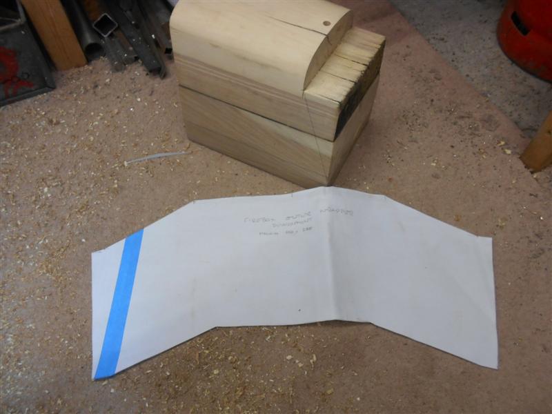
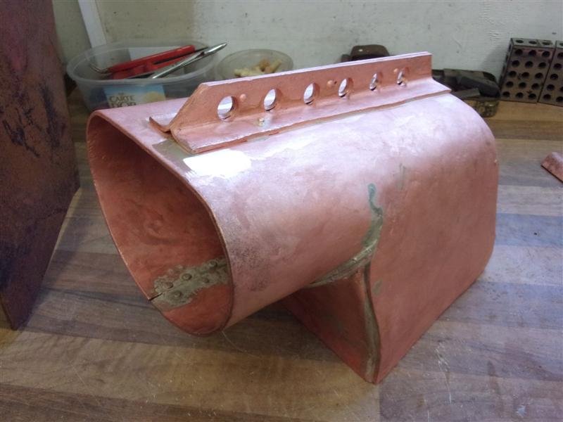
I have made the former for the outer wrapper of the firebox
using a couple of lengths cut from a railway sleeper, screwed together and
then hand-sawn to form the tapered shape. It's a big box and needed a few
hours work to produce. Cardboard templates were made of the top of the firebox
by tracing from the drawing, marked onto the former and then profiled with
a plane and orbital sander. The angles for the backhead and the bottom of
the box were marked onto the former next. A large piece of paper was then
placed over the former and the lines transferred to the paper, giving me
a flat layout, or development, of the wrapper. This came out at 608mm x
280mm, quite a big lump of copper. |
 |
 |
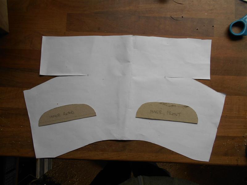
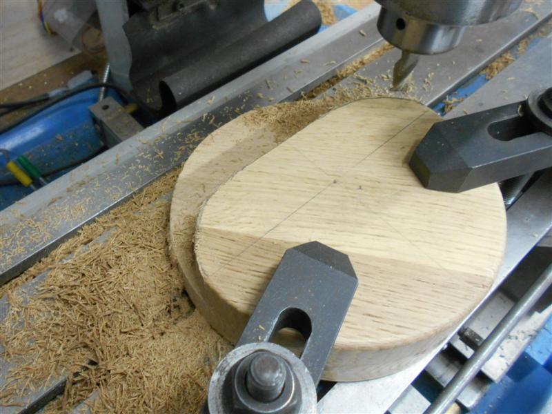
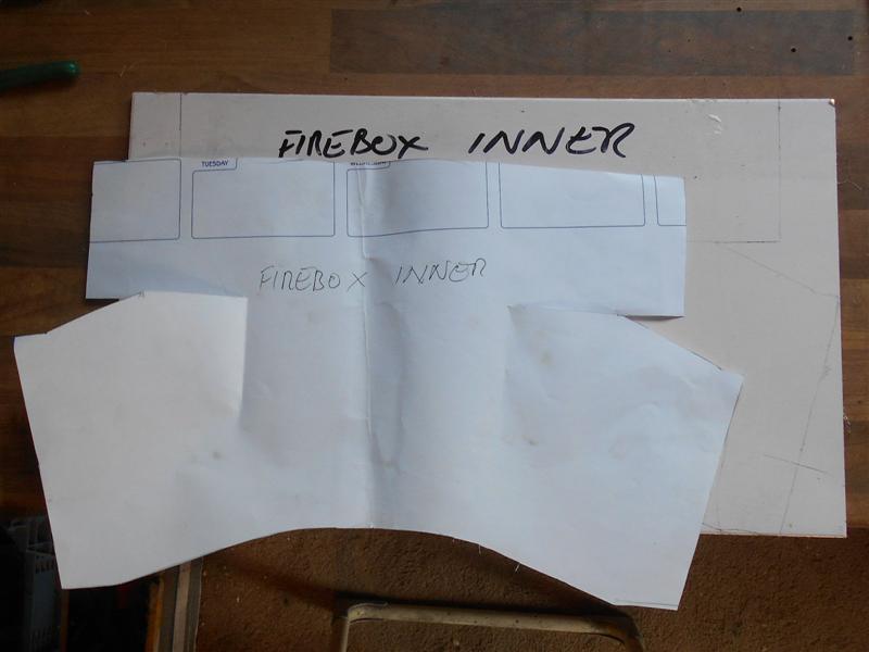
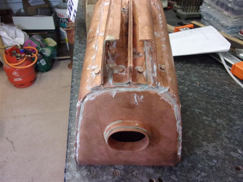
The former for the firebox inner was made in a similar
fashion but with a separate piece at the front for the combustion chamber.
This was turned to 5.1/2" diameter and then screwed to the inner former,
aligned with the boiler centre-line. Although I started with a HSS tool,
one of the pictures shows a polished carbide tip in use once space permitted.
These are super-sharp and work well turning wood. |
 |
 |
This time, the development had to include the wrap-around
section for the combustion chamber which is joined with a strap at the bottom.
For this the copper needs to be 462mm x 280mm. |
 |
| 3. Flanging Plates |
|
|
 |
The various flanging plates have been made from an offcut
of 40mm laminated oak kitchen worktop. The shapes were marked out, allowing
for any bends in the plates, then cut with a jigsaw. The backhead plate
needed some extra shaping and this was done on the mill. Because of it's
size different workholding methods were needed; the first angle was created
by clamping direct to the table, the other two by screwing a piece of box-section
mild steel to the reverse and holding in the tilt-and-turn vice. |
 |
 |
The combustion chamber front plate and the firebox backplate
were made in a similar manner to the backhead plate. The front tubeplate
former has been made as a double-duty item with the rear tube plate on the
rear. If this doesnt work, I will need to split them in two. |
 |
 |
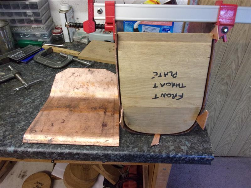
The front throat plate was the largest of the formers
and the most challenging to make because the drawing section is staggered.
Once finshed, I noticed that the milling cutter and collet in the mill had
tarnished overnight where I failed to clean down properly. There must be
something in the oak that affects the steel - I must be more thorough in
cleaning up afterwards when machining hardwoods. |
 |
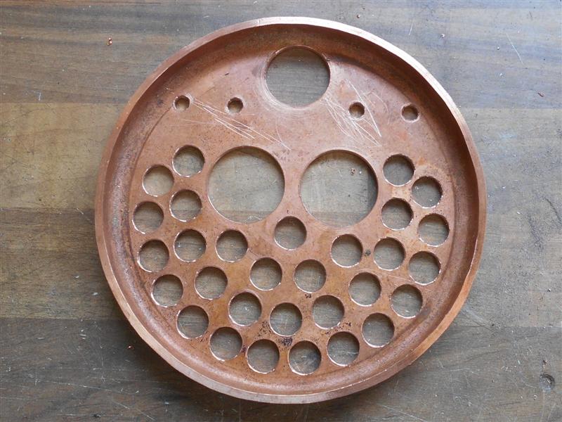
| 3. Rear and Front Tube Plates |
|
 |
I chose to make the rear tube plate first because it is
one of the smallest items and not too expensive to replace if I messed it
up.The rear tube plate was cut to shape from a 129mm x 178mm piece of 1/8"
copper sheet. After that, the plate was annealed and the forming began.
I started with a rubber mallet but changed to a steel hammer and hardwood
drift after a short while. Couldn't get enough movement with the rubber
mallet. I found that a backing piece was essential to stop the flat area
deforming. |
 |
 |
It took me four further heat-ups to get the plate fully
formed. Then I clamped it to the mill table and trimmed the flange height
to half an inch. I'm not going to put the holes in until I have sourced
the superheater flue tubes in case I get the hole size wrong. The next part
I made was the front tube plate, marking out the 7" dia circle on the 178mm
guillotined blank. Then I hacksawed away the waste and followed with a first
heat-up to bright red and quenching in water to get the blank nice and malleable. |
 |
 |
As before, the flange was slowly formed around the former,
working until resistance was felt. The workpiece was then reheated and quenched
before forming continued, this cycle of working and then annealing continuing
until complete. This one took five reheats before I finished. The flange
was trimmed to 7/16" long in the lathe using a polished carbide for the
cut. |
 |
| 4. Boiler Barrel |
|
|
 |
The drawing shows a develpment of the boiler shell and
the first thing to say is that the dimensions are rubbish. The 19.9/16"
dimension should be 19.1/4" and the 21.3/8" dimension should be 20.3/4".
These dimensions were duly marked out on the blank sheet and the waste removed.
I don't have a bandsaw but a good-quality blade in my jigsaw worked fine,
brushing on some suds to help lubricate the cut and keep it cool. The edges
were then filed to a good finish with particular care to the edges forming
the bottom join. |
 |
 |
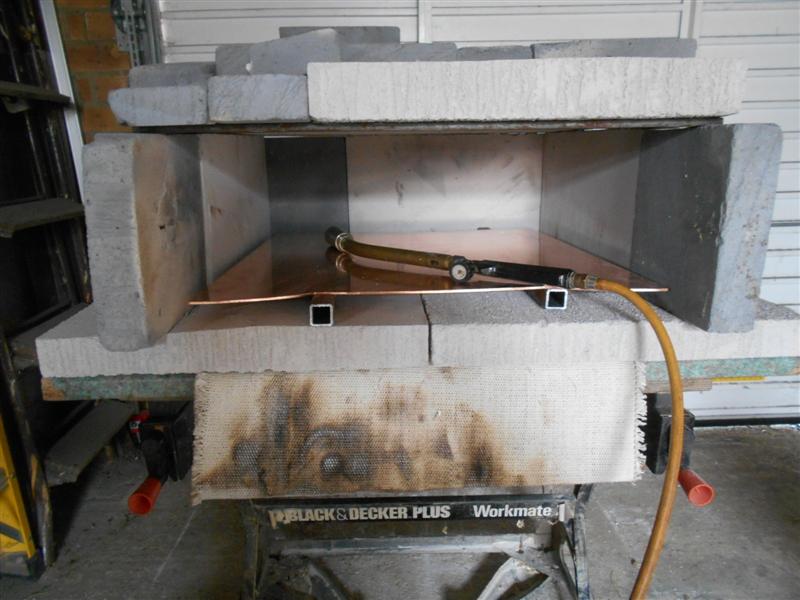
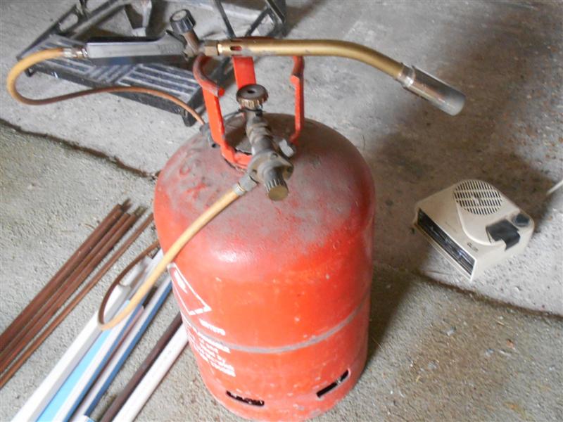
Next, it was annealed in my temporary home-made kiln using
a propane cyclone burner because it doesn't get starved of air as easily
as normal burners. However, it's a big lump and took ages to get hot. I
think I need the next size up. I had to let it cool naturally as I don't
have a village pond nearby, then it was into the rollers and much heaving
and grunting as the barrel was rolled. |
 |
 |
Halfway through I removed the workpiece for another heat-up
before finishing the roll. It looks easy but is actually quite hard work.
Aside from the waiting time whilst cooling, I must have spent a good two
to three hours on it. I then spent another hour or so teasing it to the
final shape, the two flats at each end of the roll being hammered to shape.
I made an anvil from an old acetylene gas bottle that I scrounged from the
local gas stockist but I was hoping to find a length of old telegraph pole. |
 |
 |
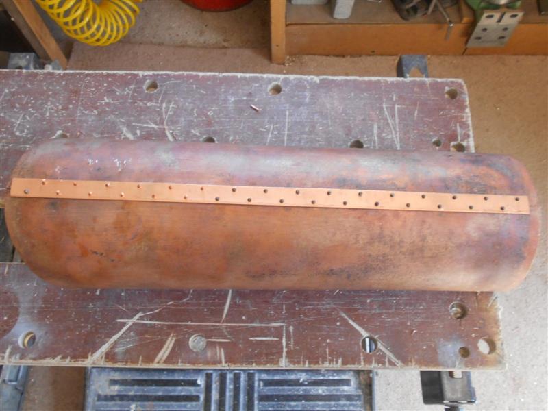
I also had to file out some more material from the join
to get the sizes at the ends correct and I made a couple of plugs from the
oak offcuts to fit each end, rather than using the tube plates. Just a little
more to be filed out at the front for a really tight fit. After that, the
boiler strap was drilled as per drawing and held in place on the boiler
shell seam under the rachet straps. |
 |
 |
With the straps pulled up really tight to keep the seam
closed, the holes were drilled through in turn with a pistol drill and a
3/32" steel rivet dropped in. Once all the holes were drill and the rivets
were keeping the seams together, each rivet was removed in turn, the hole
deburred and a copper rivet inserted from the inside. The picture isn't
very good but I'm half-way through swapping the rivets. Once all the copper
rivets were in place, the barrel was once more placed on the acetylene cylinder
anvil and the rivets trimmed and belted flat into the countersinks. The
strap was eased to the shape of the boiler at the same time. |
 |
| 5. Tube Plate Holes |
|
|
 |
The drawing only shows guide dimensions and I found it
easier to measure the tube centres on the drawing and transfer these numbers
to a larger sketch. CAD users will, of course, just be able to lay these
out on the screen and print out the numbers. Because we only get one shot
at this, I decided to drill a piece of MDF first and see how well spaced
the tubes were. As you can see, a few of the holes are a bit too close together
so I moved the various tubes to suit and entered the new dimensions to the
sketch. |
 |
 |
The rear tube plate was then clamped onto another piece
of MDF, centred up and the holes drilled and reamed using the DRO for accurate
positioning. The 1.1/4" superheater flue holes were step-drilled up to about
an inch and the boring head used to bring them to final size. After a bit
of a clean-up and deburr, this is the other side. The tubes are a tight
fit at the moment, which is what I wanted, and I shall skim a few thou off
the tubes to create a shoulder for a positive location prior to soldering.
The front plate was made in a similar fashion. |
 |
| 5. Boiler tubes |
|
|
 |
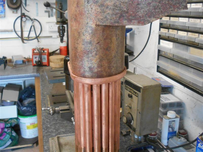
The boiler tubes were initially cut using a plumbers pipe
cutter and then faced to length in the lathe using a backstop fitted to
the rear of the spindle. They were then returned to the lathe and the ends
turned down by a few thou for a sliding fit into the two tubeplates. My
ER25 collet adapter came in useful because it allows the work to pass right
through, unlike the 3MT lathe fitting. Here is a trial fitting of the tubes
in the rear tube plate. |
 |
 |
The two superheater tubes were faced to length in the
lathe and then spigotted either end in a similar fashion to the boiler tubes.
Because I don't have a fixed or travelling steady - I haven't done anything
further with the big steady I made for the smokebox yet - I made a quick
bearing and collar to fit in the bore of the tube. This supported the end
whilst facing to length but a traditional centre was used to support the
work for turning the spigots. |
 |
 |
Thirty pegs of differing lengths were made from 14mm
wooden dowel to assist with locating the tubes in the front tubeplate. The
shouldered section to fit the tubes was turned first, follew by parting
off to varying lengths. They were then set in a short length of pipe to
support the back of the collet and the taper turned using the compound slide,
changing the angle to suit the length. It worked but was a lot of faffing
around. |
 |
| Once all the tubes were assembled into the
two tube plates, solder rings were placed over each of the tubes before
smothering the whole lot in flux. I have some 38 percent medium temperature
silver-solder for this first operation. This is to allow a lower-temperature
silver solder to be used when joining the tubeplate to the combustion chamber.
Only the rear tubeplate will be soldered at this stage, the front tubeplate
is the wrong way round at present and just being used for support. |
 |
 |
After smothering the plate in HT5 flux, the assembly was
brought up to temperature by applying heat to the underside of the tubeplate
and rotating the assembly by hand. I had it stood on a piece of steel inside
an enclosure of Celcon-style blocks and had to get it to cherry red before
the solder would flow. Once cool, I gave it a thorough clean in hot soapy
water, then pickled in Citric Acid until bright pink copper showed everywhere.
A few tubes near the centre hadn't taken the solder so the whole thing was
fluxed up again and another heat-up undertaken to get the last few tubes
secure. |
 |
| 6. Firebox Inner Wrapper |
|
|
 |
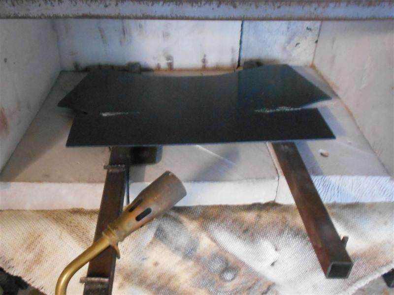
The development outline of the inner firebox was marked
out using a paper template that I created by wrapping it around the wooden
former. The waste was then removed with a jigsaw, the plastic protection
peeled off and the workpiece annealed. I used a bigger torch this time and
got the copper up to red heat in about three or four minutes. |
 |
 |
It needed two more reheats before I was able to reach
this stage and then it was a case of easing the combustion chamber to final
shape for a snug fit inside the tubeplate. The throatplate will be made
next so that the firebox can be fitted to the shape. However, I have made
a mistake here and it needed some additional work to achieve a satisfactory
outcome. |
 |
 |
Before I started building the boiler, I obviously
did some research on the internet and one of the things I came across quite
early was a set of pictures from Station Road Steam showing a set of formers
and a collection of cut plates that they had for sale way back in 2007.
I promptly downloaded these pictures and have used them as a casual reference
since. In this instance, however, the person who cut the plates made a mistake
with the firebox wrapper, specifically the cut line from the base up to
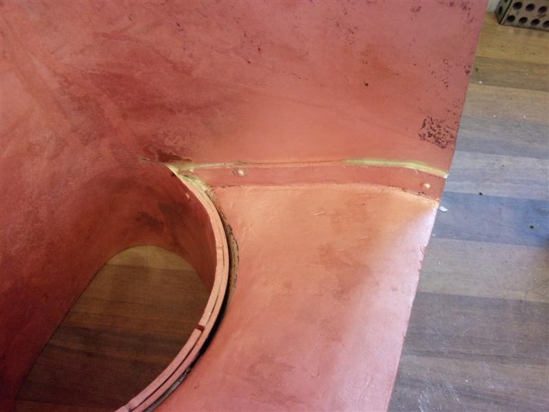
the combustion chamber. Because the front of the firebox slopes up and forwards,
the combustion chamber needs more material at the bottom than the top. The
paper template that I made produced the effect shown on the left, revealing
a gap between the throatplate and the lower part of the combustion chamber. |
 |
What I should have done is shown with these two sketches.
Points A - A are created by projecting the angled front throatplate up to
the centreline of the boiler. I fell into the same trap that the other person
did but, in my case, because I chose to make a flanged throatplate this
covered the gap that would have been left if I has made the butt-join throatplate
instead. |
 |
 |
The throatplate has to come forward at the top but it
will still leave the angle a little too upright. This won't matter, however,
it just increases the water space at the top of the plate, but it did require
a strap around the underside of the combustion chamber. The soldering has
been done in stages with 38 percent silver solder, the joining strap first,
followed by the packing strap. Next, the throatplate was held in place with
four copper rivets and the first side soldered. |
 |
 |
These are the only two photos I've taken
of this part of the build. The heat was applied to the inside of the box
and the solder was rested on the outside of the box and covered with HT5
flux. My soldering won't win any beauty prizes but at least I can see that
full penetration has occurred and I'm happy with the joint. |
 |
| 7. Inner Backplate |
|
|
 |
The backplate for the firebox inner is one of the smallest
pieces coming in at a mere 188mm x 160mm. It was duly marked out around
the former like all the others. Same procedures as before and this is the
finished backplate having a test fitting. |
 |
 |
The firehole ring gets soldered into this before the backplate
is assembled and that was made next. The drawing shows a piece of 14swg
tube wrapped with a 10swg ring and, luckily, I had a suitable piece of 2"
OD tube in stock for the inner. To create the outer, I calculated the circumference
and milled up a piece of copper to suit. After bending, and finding it too
short, a new piece was made 3/16" longer. I've obviously forgotten how to
calculate. |
 |
 |
This was annealed before wrapping around the tube. Then
the ends were soldered together in the vice with medium-temperature (38%)
silver solder. Finally, the two parts were lined up and a pair of 3/32"
holes drilled and copper pins fitted to keep the rings in place. Then they
were soldered together before turning both ends to length in the lathe.
One tip to offer others: don't try and turn the thin-walled copper tube
in a 3-jaw chuck without some additional support. I distorted my first piece
of tube and had to bin it. After the ring was soldered on, it was much more
rigid. |
 |
 |
Finally, the firehole ring was squashed to shape in the
vice and the shape marked onto the backplate. The hole was stitch-drilled
freehand with a 3mm PCB drill. This time, I just chiselled out the waste
piece and filed to size. |
 |
 |
Before soldering the firehole ring into place, I secured
the backplate to the firebox and drilled four rivet holes, two each side,
for holding in place during soldering. Because of the angled back, the backplate
wanted to keep falling inwards to the firebox and the packer clamped to
the crown stopped this happening. Finally, the firehole ring was soldered
into place.. |
 |
 |
With the help of a colleague we were able to get two burners
working on the inner firebox, working one side each and letting the heat
flow round to the back. The firebox is set up with its firehole resting
on a couple of blocks to get the heat in from below and the solder has been
preformed and rested on the edge of the backplate inside. Flux was laid
around the pre-solderded firehole and also over the rivets, inside and outside.
As many blocks as possible were laid around and over the top as we could
get without impeding the torches. After a good clean-up, this is the final
result. |
 |
| 8. Firebox Outer Wrapper |
|
|
 |
The firebox outer wrapper is the second largest piece
of copper, coming in at 608mm x 280mm and was duly marked out by drawing
round a paper pattern. As before, the waste was removed using a jigsaw,
leaving a little extra on the bottom edges, and then brought up to temperature
for annealing. I've found that it is sufficient to reach dull red or a little
brighter to soften the copper. Going higher into the cherry reds doesn't
make the workpiece any softer, or remain maleable any longer, so is just
a waste of gas. First bends were made by resting the workpiece on top of
the former and just pressing down. This caused the crown to rise a little
and subsequent forming was done under my press. I only used this because
I don't have a clamp long or deep enough to keep the top in contact with
the former. |
 |
The sides were eased down using a hide mallet and after
two more reheats arrived at the point where I could hold the bottom edges
in place with a pair of sash cramps. This can be left like this while I
cut the front throatplate. Then the wrapper can be eased to the final shape. |
 |
| 9. Front Throatplate |
|
|
 |
I decided to put the two bends in the front throat plate
before cutting to shape, the lower section being held between two lumps
of steel held in the vice. The upper, reverse bend was folded around the
former to get the basic shape but the former is not quite right and an allowance
has been made to compensate. |
 |
 |
The bend needed to be higher and is now in the right place.
The two bends were adjusted until the plate could be stood on the drawing
and matched the draughtsman's lines. Then the outline of the former was
marked on the plate, the flange allowance marked and the waste removed.
After cutting, and before the flanging started, a sanity check was made
by resting the firebox outer wrapper on the throat plate to make sure I
was in the right ballpark. |
 |
 |
The former was also double-checked to make sure that it
fitted the outer wrapper correctly. the packing pieces are there to simulate
the flanges. Now it's time to get on and form the flanges but I shall need
to make some new formers. These fancy-shaped formers that I made are fine
for getting a visual outline of the final shape but rubbish for clamping
down on because of the angle. These are the two formers that I used to form
the flanges around. This oak worktop has certainly come in useful. |
 |
 |
I find this one of the easiest ways to hold the plates,
and using a hardwood drift to form the shape. One thing I did find was that
the plate was trying to straighten itself when I was working the area around
the fold lines. I had to put the throatplate in the vice between two lumps
of steel and get the angle back to thirty degrees. This, in turn, caused
the edges to splay out again. I also re-annealed this plate about seven
times before I was happy with the finished article. |
 |
 |
Here it is, offered up to the firebox outer wrapper. It's
slightly askew but will be simple to ease into the correct shape. And two
views from the side and the inside. |
 |
 |
Moving on, the barrel was offered up to the front throatplate
and a pencil line drawn around to mark the cutaway. A felt-tip pen was then
used to mark inside this line and was used as a drilling guide. The workpiece
was mounted on the mill under timber packers and a 3mm PCB drill loaded
up. Because of it's rigidity no centre-drilling was needed. I stitch-drilled
the first half of the plate. |
 |
 |
The upper section was drilled in two stages, swapping
the single clamp to the other side half-way through. To clear the waste
from the centre, I chose to use some old Abrafiles that I have and had to
modify my hacksaw to take them as the original frame has been lost during
various moves. The advantage of these is they can be used at any angle and
don't break if the frame is twisted. |
 |
 |
About five minutes work to cut the centre section away.
Then it was onto the careful job of dressing to make a nice fit around the
barrel. This took quite a time as I didn't want to go too far and have to
try and fill any excessively large gaps. Emery bands in the Dremmel were
used for this job. I managed to get the front throatplate filed up to a
good fit today but, as expected, it took a lot of effort to get a really
nice, tight join. |
 |
 |
The front throat plate was clamped to the mill bed and
the side flanges reduced to just over a half-inch high. Although the usual
way to join these is to just solder the tube into the tubeplate, I didn't
really feel this was good enough. I decided, therefore, to make some form
of collar to butt the front plate up to and three pieces of copper were
milled to 1/4" wide and shaped to fit around the barrel. |
 |
 |
The front plate was placed on the barrel and adjusted
until the various lengths agreed with the drawing and a pencil line drawn
around the periphery. The strips were then lightly clamped to the barrel,
pushed and shoved till they matched the drawn lines, then clamped tight.
3/32" holes were drilled at various positions and rivets temporarily fitted
to hold the straps. Once happy with the position, the rivets were reversed
(heads inside) and hammered flat into countersinks on the outside. There
is loads of space under the cleading and these straps will not interfere
with the fit. In fact, they will help. |
 |
 |
The white dots on the straps are a series of 8BA holes
that I have drilled through the straps and filled with correction fluid.
They will be available for fitting studs to after soldering to fix the cleading
to. Whether I use them or not remains to be seen but it's easy to make provision
now rather than trying to drill and tap some blind holes later. Here is
the barrel after soldering and the tippex has stopped the solder entering
the holes. After cleaning up and filing down any surplus solder, the throat
plate was fitted onto the barrel and gently tapped around until it butted
nicely up against the strap. |
 |
 |
Finally, the inside of the barrel was peened outward until
it slightly flared over the throat plate and trapped the barrel in place.
This assembly was now mechanically sound and has been soldered together.
The greatest gain here is the fact that there are now two faces for the
solder to join, the vertical and the horizontal, and results in a far stronger
join. And I get somewhere to fix the cleading for free, if I choose to use
it. |
 |
| 10. Inner Girder Stay |
|
|
 |
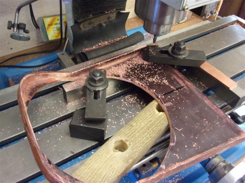
I bent up a couple of lengths of 3/4" angle from the
copper offcuts, shaped the ends and drilled the six half-inch clearance
holes for the cross-stays, remembering they are left- and right-handed.
Next they were clamped together, three 3/32" holes drilled and then riveted
with copper rivets. These are entirely within the water space and need no
special attention. I then stood the assembly in the upright "T" position,
laid a length of high temperature silver solder in the gulley and did a
cook-up. They don't really need soldering together but it did have the added
advantage of annealing the copper again. The assembly was then placed on
top of the firebox, clamped at the front and a pair of 3/32" rivet holes
drilled right through, one front and one back, to keep the girder in position
during soldering. |
 |
 |
Rivets were loosely laid in the holes with a tiny ring
of solder underneath and the girder melded to the top of the firebox. It
was then set up in the hearth at about thirty degrees with a couple of lengths
of solder up the gully for the lower leg and one on the top edge for the
upper leg. Heating was done from inside the firebox and below the girder
until we had a full melt. After the box had cooled for five minutes, the
cinder blocks were cleared away to speed up cooling. As can be seen, the
rivets are standing proud of the girder where the solder melted away, and
these can be dressed back. Full penetration has occured with solder visible
inside the firebox. |
 |
| 11. Outer Girder Stays |
|
|
 |
The outer girders were marked out on the plate then cut
to shape with a hacksaw. These will not be machined, plus or minus a sixteenth
of an inch is fine for this. |
 |
 |
A couple of sessions of annealing and bending got to here
continuing until they matched the end view on the drawing. Then they were
set up on the mill and the half-inch holes drilled as before. When fixed
to the top of the firebox, these holes need to be aligned to allow the cross-stays
through. |
 |
 |
Three rivet holes were drilled in each girder, then these
were clamped (with difficulty) to the top of the box and spotted through.
8BA nuts and bolts were used temporarily to hold them in place while the
bottom lips were teased to the shape of the firebox. These will be removed
and loose rivets were set in prior to soldering. If I were to do this again,
I would get these girders affixed before putting the firebox backplate in,
this would make it much easier to position and clamp the girders to the
top of the box. As it was, I was faffing around a good while before I was
happy with the job. |
 |
 |
I set the firebox up in the hearth tipped over to about
thirty degrees and laid solder on the the top of the join on the upper one
and in the gulley of the lower one. Heat was applied from below each component
until the solder melted and wicked down into the joint. However, I didn't
bend the rivets over enough and the top one lifted a little at the end and
I wasn't happy with the joint. The lower one was better but I should have
used more solder and daylight could be seen in a couple of places under
both girders. I decided to revisit both joints and started with a really
good clean up and pickle to try and get everything scrupulously clean. After
tapping down the wider gaps the assembly was fluxed up again but the existing
solder got in the way of getting the ends down tighter. |
| During the second heat-up, I noticed that
I was putting in more heat than before and that the solder under the girder
was starting to re-melt but, more importantly, the solder around the top
corner of the backplate was starting to go semi-liquid and I backed off
straight away. After cooling, cleaning and pickling, I could see that the
heat had also lifted the central girder slightly away from the top of the
box at the back and, by now I was wary of another cook-up in case I made
matters even worse. I decided to drill and tap four new holes, one in each
girder at the firehole end, and some sloppy 4BA bronze screws were made.
These were fluxed, then screwed down touch-tight and the whole assembly
fully fluxed up again. |
 |
 |
Rings of solder were placed around the screwheads and
solder laid in the gulleys as before, including some in the centre girder
and on top of it. Then my colleague and I applied heat from two torches,
one of us concentrating on the top part and one on the lower. Once we were
up to melt temperature, one torch was removed and the other used alone to
draw the solder down into the joint. We were in better control of things
this time compared to when I went it alone and we now have solder along
all the joins with no daylight showing. This is the lower girder but the
others are similar. |
 |
| 12. Dome Bush |
|
|
 |
The drawings show that the dome bush is optional on Britannia
because the regulator is in the smokebox. I was going to omit the dome bush
but John the Pump suggested that it would be useful as a means of flushing
out the boiler - nice, big hole - and it could do the additional duty of
supporting the steam collector pipe instead of adding another small hole
in the boiler shell further along. There are no dimensions given for the
bush, just an outline on the drawing of the shell so I scaled from this
instead, then modified to suit my needs. The bush and it's cover plate were
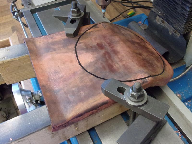
made from bronze offcuts starting with the bush. A hole saw was used to
remove the centre and a parting tool modified to trepan the outer size. |
 |
 |
The turning of the bush was quite straightforward and
the component was then set up on the mill to drill and tap eight 4BA blind
holes for the cover plate. I chose a 2" PCD so the hole positions were simply
"1.0, 0.0" and "0.707, 0.707" respectively. The cover plate was machined
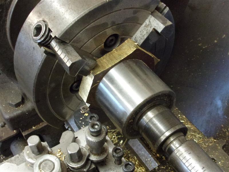
from a weirdly-shaped offcut of bronze using the four-jaw chuck. The old
wheel bearing came in handy for extending the centre to provide support
against the intermittent cut. |
 |
 |
The packing pieces between the jaws and the workpiece
were to create enough room for the turning tool to function without clouting
the jaws. Second op. was undertaken using soft jaws, bringing the flange
thickness to size and maching the spigot for a good fit in the the bore
of the dome bush. Then it went to the mill to be drilled - same settings
as the dome bush - and finally back to the lathe to be face to length. I've
stopped at this point as I haven't yet decided whether to use a gasket or
an O-ring for sealing, it will get pretty hot here. |
 |
| 13. Inner Assembly |
|
|
 |
When the time came to join the tube assembly to the firebox
inner, the front of the combustion chamber was manipulated until it was
a snug fit inside the rear tube plate flange. This mostly involved flaring
the edges of the chamber outwards, effectively stretching the metal a little,
and letting the tube plate force the combustion chamber back to shape. Prior
to setting up in the hearth, a strap was made to hold the two parts together
and set the angle of the tubes correctly. On the drawing a line was projected
forward from the underside of the girders to the front of the tubeplate
and the distance from this line to the outside of the front tubeplate measured.
A length of 8mm x 40mm flat steel was cut to length, a spacing piece drilled
and then welded on. This was then lightly clamped to the inside of the girder
stays and bolted to the front tube plate with a spacer between to set the
correct distance, allowing for the thickness of the strap. |
 |
 |
The overall length was checked and the girder clamps tightened
up. The whole assembly was then set up in the hearth, well-fluxed and with
1.5mm dia 55% solder sitting on the rim. 2mm dia would have been better
but I have none. Heat was applied to the underside edge of the combustion
chamber tubeplate, chasing the melt around the top. Because we were close
to the girder stays, we refluxed those joints as well, just in case they
started to soften and also the tube ends nearest the edge. |
 |
 |
Once the resting solder had melted, extra solder was added
by hand until there was a good, filled joint all round. After cleaning and
pickling, this is the result. The tubes are fine because high-temp 38% solder
was used for those and the reheat has not disturbed them at all. It is more
usual to solder the firebox together first and the tubes added after but,
because of the depth of the combustion chamber, I thought it easier to do
it this way. The last photo shows how difficult it would be to solder the
tubes to the tubeplate after it is in situ. |
 |
| 14. Other Boiler Bushes |
|
|
 |
I have now made all the bushes needed for the boiler,
using either phosphor-bronze bar or offcuts of the unknown bronze plate
that the smokebox door is made of. The clack, safety valve, blowdown and
water gauge bushes were all straightforward turning with threads tapped
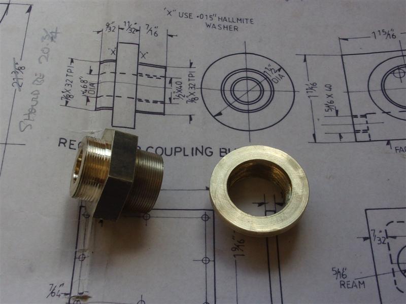
to suit. The regulator bush and it's coupling nipple have a 7/8" x 32 tpi
thread and these were turned and screwcut on the lathe. The bush was made
first, turning the top-hat form and machining the bore to 0.835" diameter,
the nominal depth of thread for a 32 tpi Whit form thread being 20 thou.
The bush was reversed in the chuck and a small register machined in the
bore to allow the coupling nipple to screw up tight. Then, using a Whitworth-form
screwcutting insert, the threading tool was touched on the bore and the
dial zeroed. Multiple passes were made until I was seeing 40 thou (diametric)
on the dial and a few spring passes made to finish. |
 |
 |
The thread should be slightly undersize at this setting
and if I need to aquire a tap to clean out the thread at some point in the
future, there should be enough material to clean up. I made the coupling
nipple from hex bronze bar only because I have quite a lot of it. The end
with the longer thread was turned first and the thread was screwcut right
up to the shoulder, unpowered and pulling the chuck round by hand. The bush
was used as a gauge, aiming for a free-running fit. The final size was marked
on the cross-slide dial ready for making the other end. The component was
drilled through and the 1/2" x 40 tpi thread for the steam collector pipe
tapped at the same time. |
 |
 |
To make the other end I used the bush as a mandrel to
protect the original thread but that meant the gauge was no longer available,
hence the marking of the dial. As it turned out the thread was a little
oversize so it was held gently in the chuck with a turn of emery cloth for
protection and the thread chase freehand until the correct size was obtained.
Not so easy with a single-point tool and a machine with no reverse on it. |
 |
| 15. Boiler Bush Holes |
|
|
 |
The various holes in the boiler shell for the bushes were
next and I started by marking out the centreline along the top of the shell
and measuring off the distances required. Because the drawing gives dimensions
as a linear distance around the circumference a card template was made with
the distances marked off. Using a template in this manner ensures that the
holes are square to the centreline. Prior to drilling the holes, I fitted
the front bung to prevent collapse of the tube when clamped to the mill.
With all the handling recently it had gone a little out of shape and needed
to be adjusted to fit the front tube plate anyway. |
 |
 |
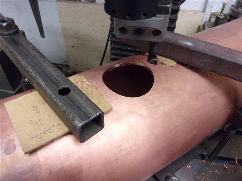
The dome bush hole was set up first and, as can be seen,
it's a bit of a squeeze to get it on the mill. The boiler shell is resting
on a pair of clamped steel angles, clamped with whatever was to hand and
centred. This one is a big hole and, after piloting with a holesaw, was
cut using a boring head. I had to change the tool position half-way through
as the head adjustment ran out of travel. |
 |
 |
The top feed bushes needed a pair of 5/8" diameter holes
and these were formed with a step-drill. Standard twist drills are a poor
choice for drilling copper because of their tendency to grab the work and
pull themselves in. The two safety valve holes required 3/4" diameter holes
and these were done in similar fashion but using the bench drill instead
of the mill - not enough clearance on the mill to accomodate the throat
plate. Again, with hindsight, it might have been smarter to make these holes
before the throatplate was soldered on. |
 |
| 16. Next Item ... |
|
|
| |
|
|
| 16. Outer Wrapper |
|
|
 |
I was not happy with the shape of the firebox outer wrapper
and had ordered a new piece of copper to try again. I redrew the angles
onto the firebox former and made a new paper template to mark out the copper.
I'm much happier with this second try. The angles of the front throat plate,
backhead and the fire grate are much more accurate now. After getting the
wrapper to be a nice fit around the front throatplate I set the assembly
upside down on the bench and packed the front end to 7/16" high and the
back to 3/8". This gives the correct shape to the top of the boiler. |
 |
 |
The throatplate had to be eased back a little to match
the bottom of the wrapper correctly and the wrapper needs a little trimmed
from the bottom angles. The backhead was offered in next and the firebox
tapped around until a nice fit was obtained, then clamped in place. The
backhead needs to be trimmed to length and this was duly marked off. |
 |
 |
The backhead also needs the lower bend enhanced a little
and this will be annealed and reworked. Checking the length from the front
of the barrel to the front of the throatplate showed it to be about 1/4"
too long but, as can be seen in the picture, after the front of the barrel
is trued up, this will come right. |
 |
 |
After the difficulty experienced with the outer girder
stays, I decided that the outer wrapper would be fixed to the front throat
plate with screws. I have some 4BA hex bronze bar in stock so this was chosen
as the size and a good handfull of screws made. Starting at the top of the
wrapper, I drilled a 2.5mm hole right through with the pistol drill, opened
it up to the 3mm tapping size, opened the wrapper part to 3.7mm with a hand
drill and tapped the 4BA hole freehand. I drilled the 2.5mm pilot hole because
I didn't want the tapping drill to cut oversize. This was temporarily bolted
with a steel screw whilst the other holes were made in turn. |
 |
 |
Meanwhile, I have also soldered the various bushes to
the boiler barrel using the same 38% silver solder. The wrapper was refitted
to the throat plate with the steel screws and the flange of the throat plate
tapped about and the screws tightened a little more until there appeared
to be good contact at all points. From the outside, the wrapper was tapped
gently down onto the throat plate, letting it follow the curve of the flange. |
 |
 |
To start, we dismantled the assembly and gave a quick
rub with some wire wool to the surfaces that were to be soldered and a wipe
over with a cloth. It was still clean from the session in the pickle last
week and didn't require any more than this. A small amount of flux was painted
around the inside edge of the wrapper. Flux was also painted on the flange
of the throatplate and over all the nearby solder joints, including both
inside and outside of the throatplate-to-barrel solderwork. |
 |
 |
Solder was cut to size and bent to shape to rest on the
edge of the flange all the way round the inside. This took quite a while
to get it all sitting nicely but it's worth the effort to ensure it doesn't
fall off during the heat-up. There are four or five separate pieces of solder
here. More flux was smeared over the solder and the assembly carried through
and stood up on the hearth. Blocks were stood all round to encase the barrel
and a further one (not in the picture) sat on top to stop the heat wasting
away out the top. |
 |
 |
Using both torches with a low-power flame,
gentle heat was applied evenly all round to the underside of the throatplate
until the water had boiled off from the flux. In the past, we've put the
heat in too quickly and the rapid boiling has dislodged the solder. Once
any bubbling had ceased, we turned up the power and rapidly got the assembly
up to just before dull red. At this point, we concentrated the heat near
the right-hand clamp and waited until we saw the solder melt, then slowly
moved the heat around the underside chasing the solder. As it melted, it
was easy to see when to move the torches along and work our way around the
throatplate to the left-hand clamp. This picture was taken about thirty
seconds after removing the heat. |
| A few minutes later, we removed the blocks
from around the assembly and left it to cool naturally until it could be
moved by bare hands. After a gentle scrub in the rinse tank, it was moved
to the pickle tank. Back on the bench, we checked the screws to see if they
had been soldered but half came out easily and the other half with a small
amount of effort. Each of the holes was retapped, the screws given a quick
pickle, flux poked into each hole and the screws put back in. This time,
a horse shoe of solder was placed on each screw head, nipped on, completely
refluxed again and the whole lot carried back to the hearth. I changed my
burner nozzle for the cyclone burner and away we went again, my colleague
heating just below the throat plate and me heating the flange of the throatplate
inside the firebox. Once up to temperature, heat was concentrated on each
screw in turn until melting had occured. |
 |
 |
The cyclone burner was needed inside the firebox because
a normal burner quickly starves itself of the available air and goes out
whereas a cyclone burner gets it's air from much further back and stays
alight in the confined space. After a final wash-off and a good long soak
in the pickle, these pictures show the results. The first one shows that
all the solder has melted and flowed right through the joint and the second
shows the screws satisfactorily sealed. |
 |
| 17. Backhead |
|
|
 |
The backhead plate has been made in similar fashion to
all the other plates and not worth repeating here. It has already been seen
in the trial assembly of the outer firebox. Although it will be one of the
last items to solder in place, I have been preparing the holes for the bushes
as these need to be machined rather than just drilled. As can be seen, the
lower gauge glass bushes are set at about twenty degrees on the angled face.
A 7/16" slot drill would have done the job but, not having one, I chose
to bore them to size instead. A 10mm slot drill was used as pilot. I also
drilled and tapped the four holes for the longitudinal stays. |
 |
 |
To assist with getting the bushes in the correct place,
I made a jig from an offcut of copper, drilled 1/4" clearance holes at the
bush centres and drilled and tapped three M5 holes to take some stand-off
screws. I also made some bronze plugs to go through the plate and screw
into the bushes and these will be retained as blanking plugs for use at
pressure-test time. M5 cap screws will act as adjustable spacers to get
the position of the bushes correct. They need to be level to ensure that
no undue pressure is exerted on the gauge glasses. These will be soldered
into place just prior to final fitting of the backhead and I've still got
the lower clack bushes to drill out first. |
 |
| 18. Cross-stay Ends |
|
|
 |
The drawing suggests making the cross-stay heads from
brass but I have made mine from phoshor bronze as they protrude into the
water space. I machined the front end in a single setup, turning and threading
the O/D plus drilling and tapping the bore and, finally, parting off to
length. I also made a mandrel to screw them into from some 5/8" dia brass
bar with four flats milled onto it. |
 |
 |
It was tempting to stand this upright in the four-jaw
chuck and just wind round on the numbers but not really a smart move unless
one has a left-hand-cutting end mill. A standard end mill or slot drill
will always try and undo a right-hand thread regardless of the direction
of the cut. They were laid flat in the vice and indexed over, working in
the tightening direction. A quick file all round and these are finished,
ready for assembly and soldering. They are quite a prominent feature on
the side of the firebox. |
 |
| 19. Boiler Assembly |
|
|
 |
One thing that has been noticeable is that the tubes are
very soft and have slowly bunched together near the base due to handling.
Now that I'm preparing to bring the two sub-assemblies together, I need
to get the tubes back to their proper position and have made another front
plate from the previously discarded outer wrapper. I have made the tube
holes 1/32" larger than the tubes to prevent jamming and the O/D a rattle
fit in the barrel. I couldn't use the proper front plate because the holes
are a bare half-inch and the tube-ends skimmed down by five thou to ensure
the frontplate stays put during soldering. The new plate was slowly worked
down the length of the tubes although I didn't try and force it the last
couple of inches. As the plate went down, the tops splayed out fan-like
and were squeezed back to position by hand. The new plate also protects
the tubes while I get on with positioning the two parts prior to joining.
The four screws are to withdraw the plate just prior to fitting the proper
one at soldering time. |
 |
 |
The first job was to get the position of the firebox correct
with respect to the front throat plate and get the girders in the middle
of the crown. A piece of 3/8" square mild steel was cut and used to set
the distance for the front part of the foundation ring, the clamps being
used to get the softer copper pulled into place. It was now possible to
stand the boiler upright on its nose and the centrelines of the fixing screws
were scribed on the crown. The position of each screw was centre-popped
on the line and the inner section was then teased over to the central position
and a G-clamp use to hold it in place. |
 |
 |
Using a pistol drill and hand drill the twelve 2BA holes
were drilled and tapped in similar fashion to the outer wrapper fixings
and steel screws used temporarily to hold things together. With the screws
holding the two sub-assemblies firmly together, a start was made on the
foundation ring and the first section of 3/8" square copper bar cut to length
and shaped to fit nicely into the bends of the flanges. This is sprung into
place at the moment but will be held with a couple of rivets before soldering. |
 |
 |
The next parts made were the side sections of the foundation
ring, cut to length level with the end of the firebox backplate. I've had
to thin the front section of these a little to compensate for the firebox
being about 1/32" over drawing size. Again, the clamps are used to straighten
the sides. The backhead needed the firehole cut out and for this I set the
backhead in place and scribed round the inside of the firehole ring from
inside the firebox. A felt-tip pen was used to ink a line about 1/16" all
round and the hole cut and filed until the ink had gone. |
 |
 |
Then it was slowly dressed with sanding drums until a
snug fit was obtained, probably taking me about a half hour to do this.
I don't want to be filling large holes here, particularly. With the backhead
clamped in place, the firebox backplate was eased back with a hide mallet
to bring the firehole slightly forward for a flat fit. I felt this was preferable
to bending the backhead in slightly. I also scribed the front edges of the
backhead flanges onto the outer wrapper. |
 |
 |
With this all done, it was time to make the backhead a
snug fit to the outer wrapper and the whole lot was stripped back and the
backhead set in place without the tube assembly in situ. First, the backhead
was clamped to the wrapper using the scribed lines as a guide and the first
pair of screws each side drilled and tapped similar to the front section
of the outer wrapper. There was a large gap at the top that needed attending
to, as can be seen by the torch light shining through. My former obviously
wasn't made accurately enough but it doesn't matter. Working on the inside,
the flange was gently worked down onto the wrapper working inwards from
the screws. Then another hole was drilled and tapped, pulled up tight and
work continued. |
 |
 |
Part-way through I dismantled it, cleaned up the holes
and annealed the plate, then carried on. This is how it finished up, nine
screws used to hold the plate and a four-thou feeler not fitting through
anywhere. Once again, these temporary 4BA screws will be replaced with bronze
ones at soldering time. The last picture shows the boiler outer sitting
on the bench waiting for the inner section to be replaced. |
 |
 |
With the two sections brought back together, the next
job was to make the rearmost part of the foundation ring and bring the backplate
to shape. The rear angle of my inner firebox is not quite correct and I
need to use a 1/2" thick piece of material instead of 3/8" to fill the gap.
I've made a temporary filler using two pieces of material but I shall replace
this with a single piece at the appropriate time. The holes for the stays
were drilled next. The drawing calls for phoshor bronze stays, threaded
2BA and nutted in the firebox which is the old-fashioned way, using comsol
to seal the threads. I've chosen to use copper rivets silver-soldered into
place as per modern practice. After marking out grids at the given 7/8"
spacings, all the 3/16" diameter holes were drilled with a pistol drill. |
 |
 |
One of the advantages of drilling all the holes now is,
although it's unlikely at this diameter, I can strip everything down and
recover from a broken drill scenario. It's also a lot easier to deburr the
backs of the holes using a ball-shaped burr in the dremel. We will solder
the stays first because it's impossible to fit solder rings to the stays
in the water space once the the foundation ring sections are fitted. I also
needed to get the front tube plate to be a good fit and this was the perfect
opportunity as it's the last time the two sub-assemblies will be separate.
The front had gone a little out of round and was now gently teased back
to the correct shape using the front plate as a former, then the flange
of the front plate was eased outwards until a decent fit all round was obtained.
I've already soldered in the bush for the regulator block and steam collector
pipe using 38% silver solder. |
 |
 |
Although the copper rivets will be used for all other
stays, the front throatplate gap increases as it rises and the rivets are
too short. Some 3/16" copper rod was turned into stays by parting to length
and centre-popping to create a shoulder to stop the rivets falling through.
To assist assembly, a decent chamfer was filed on the front. Meanwhile,
my colleague made a load of solder rings to fit over the stays. 1mm silver
solder was wound onto a 4.4mm drill like a spring to create about a dozen
rings per length. |
 |
 |
Fitting the stays to the front throat plate took quite
a time. Starting with the two lowest ones, flux was wiped into both front
and back holes. A solder ring was held in a pair of pincers that I had specially
modified for the job, lowered into the water space and a stay pushed through
from the outside, passing through the solder ring and into the inside of
the firebox. Another solder ring was placed over the outside of the rivet
and more flux was then added both inside and outside. This whole routine
was repeated until all the front stays were in place. |
 |
 |
The boiler was carried through to the hearth and blocks
built up around it. The boiler has been placed in the inverted position
with a block under the front giving a slight backwards tilt. As can be seen,
the blowdown bush has been inserted and all of the existing solder joints
in the vicinity fluxed over. Blocks have been placed over the barrel to
keep the heat in and in the combustion chamber to protect the tube ends
from excessive heat. My colleague used the normal burner over the outside
and down into the water space, at lower than normal power and keeping the
flame moving. I was using the cyclone burner and heating the inside front
of the firebox, providing the most power. This pulled the solder through
from the outside. |
 |
 |
Here we can see that the solder rings in the water space
have melted and been drawn towards the maximum heat. The rings on the outside
have melted and been drawn through to the water space. All those pink areas
are where flux was added to help protect the existing solder joins |
 |
 |
As before, the assembly was left to cool slowly and was
then rinsed and pickled to allow a more detailed inspection of how the solder
had flowed. Inside the box there is perfect penetration. Looking into the
water space, it appeared that all the rivets had been successfully soldered.
Outside on the throatplate, however, it appears that the solder on the lower
left rivet had not formed a fillet. It looks almost like the ring fell off
before completely melting but it may be that the clearance was too great
and all the solder has flowed right through. It will need to be redone and
at the next heat-up when doing the side stays, I will try a little intense,
local heat with a different nozzle and a new solder ring. |
 |
 |
The side stays were done in a similar fashion. These
have now all been soldered in and we chose to do both sides at the same
time. There is no point covering this in detail as the setup was the same
as last time, the only minor difference being that we were able to get heat
into the waterspace more effectively from the back. A couple of pictures
taken after it was all cleaned up. |
 |
 |
One of my concerns regarding the fixing of the front tube
plate was how to ensure getting the tubes hot enough for the solder to wet
them. I decided to use the small cyclone burner because it was able to fit
through the dome bush and heat the tube plate from the underside. The top
burner is the one I usually use. The boiler was stood vertically on it's
firebox and a hearth built all around to keep the heat in. The firebox was
kept open to allow an occasional blast of heat to help keep the tubes hot
and the top three or four inches of the barrel kept clear as this is where
most of the heat would be applied. |
 |
 |
Flux was pasted around all the tube ends and in the front
plate to barrel joint, solder rings placed over all the tubes and bent rods
put in the gully. The regulator/steam collector bush was blocked to try
to keep the heat in. While I kept the cyclone burner going through the dome
bush, my colleague concentrated heat around the outside of the barrel. Eventually
we reached the point where all the solder had melted so we placed another
celcon block and on top and covered the boiler with a fire blanket to encourage
slow cooling. |
 |
 |
After cleaning up it became obvious that we had not got
enough heat into the tubes because a dozen or so of them had no solder on
them, most of it had flowed onto the tube plate. We made some more solder
rings and set up the boiler as before, along with another load of solder
in the gulley. This time I decided to use the big cyclone burner instead
to get a lot more heat inside the barrel, the main disadvantage being that
it wouldn't fit through the hole and had to be rested on the lip instead.
This picture was taken later but shows the difference in nozzle sizes. We
also removed the bung in the regulator bush to see if this would allow a
better throughput of heat. |
 |
This time, it worked a treat and these last two pictures
show a perfect melt. The small mark at eleven o'clock on the outer ring
is a shadow from a slight dip in the solder, not a blowhole. I'm well pleased
with our progress and with the end result. It's slow, for sure, but we're
learning all the time and not messing it up. |
 |
| 20. Cross Stays |
|
|
 |
The horizontal stays at the top of the firebox are quite
a dominant feature and some thought was given on fitting them accurately.
The first challenge was to get the drilled and tapped holes square to each
other taking into consideration the taper of the firebox. The boiler was
set up with the firebox sitting on 3/8" packers and the barrel supported
at the far end. With the crown level, the centreline of the holes in the
girder stays was picked up with a gauge and scribed onto the outer wrapper.
The positions of the stays were then centre-popped onto the lines on each
side. Over on the mill, I scribed the same height line onto an angle plate
and drilled and reamed a 1/2" hole to take some bushes. |
 |
 |
Next, I made up three drill bushes from 5/8" mild steel,
turned to 1/2" diameter up to a shoulder and parted off. These were turned
round and drilled 9/32", 11/32" and 3/8" respectively for a pilot drill,
sizing drill and 3/8" x 40 tap. On a spare piece of kitchen worktop, I screwed
a pair of steel angles to make parallel rails and packed the boiler up as
before, squaring it to the rails and clamping firmly at the rear. |
 |
 |
Using a 3/8" dia point that I quickly turned up, the first
centre-pop was located and the angle plate clamped to the rail. Then the
smaller bush was inserted and the pilot hole drilled using a pistol drill,
the bush changed and drilled at tapping size, finally changing to the largest
bush and tapping by hand. |
 |
 |
This was repeated for all twelve holes. After the first
hole, I also drilled and tapped an M5 hole in the top of the angle plate
for a locking screw to prevent bush rotation. Finally, the stay were made
from 1/4" dia copper rod, each one individually sized to the width of the
firebox at each point and threaded 1/4" x 40 tpi. Here are the first few
assembled into position. Only eleven stay-ends are on view in the finished
model, one being hidden under the cleading. |
 |
 |
This setup is quite simplistic and not super
accurate but it's as good as it needs to be. The threaded holes are square
to their opposite number and the stays assembled easily without causing
any distortion. These will be soldered into position at the next heat-up. |
| 21. Backhead Bushes |
|
|
 |
I've now soldered the gauge glass bushes to the backhead
with high temperature silver solder using the fixture I made earlier. I
also soldered the lower clack bushes or so I thought. A closer inspection
of the lower clack bushes revealed that the solder had failed to wet them
although it had flowed all around the back plate. A gentle tap with the
hammer and they promptly fell out. Undeterred, I cleaned up the bushes on
the lathe, cleaned out the holes in the backhead, fluxed up and had another
go. Same result! I don't know what sort of bronze I have made them from
but the rest of the material has been suitably marked up as rubbish and
some fresh ones made from a new piece of phosphor bronze. |
 |
 |
Today, the new bushes were soldered in and this time
all is well. The three anchor blocks for the floor support brackets were
also made and soldered at the same time, still using the high-temp solder,
and held from the back with 6BA countersunk brass screws. These will be
covered by the foundation ring so I don't expect a problem with dezincification. |
 |
| 22. Boiler Assembly cont. |
|
|
 |
Our next session in the workshop saw the girder stays
soldered to the crown, along with the bolt heads, and the horizontal stays
soldered into position. This was really just a caulking operation but 55%
silver solder was used throughout. The girders didn't really need soldering
as the screws do the work but we decided on a "belt and braces" approach
anyway. Everybody seems to agree that the longitudinal stays in most boilers
are superfluous but, since I'm neither willing nor able to try and prove
this with calculations, then the stays get fitted as per drawing. One of
the stays in the Britannia boiler is hollow and used as a blower stay but
it adds an unsightly carbunkle to the backhead that is not on the prototype.
|
 |
| The offending lump protrudes here under the gauges. The
other stay ends are hidden under the false backhead. The blower pipe could
be run along the outside in the rectangular trunking on the near side of
the engine but having the blower pipe inside the boiler has the advantage
of reducing condesation in the pipe and, therefore, no spurt of water from
the chimney when the blower is first applied. To try and get the best of
both worlds, I have made a blind end cap for the blower stay with a 5/32"
hole in the side, the head being 7/32" long which is the space available
behind the false backhead. The one on the right is the connector shown on
the drawing. |
 |
 |
This screws into the backhead, although it could just
as easily be straight-turned the same as any other bush, and the 5/32" copper
pipe shaped to fit onto the blower valve as normal and soldered into the
bush. The pipe (when I get some) will exit from the side of the false backhead
and, hopefully, be quite unobtrusive whilst the rest of the controls can
now be modelled more like the prototype. |
 |
 |
I've been reflecting on those over-large square stay ends
and have decided to saw the ends off because they will look awful. Shallow
dummy washout plugs will be made and fixed into the cleading at the appropriate
time. It would have been better to just use simple stays silver-soldered
in place. One thing I didn't like about the earlier boiler stays was the
size of the heads on the copper rivets. For the backhead, I have machined
eighteen of them down to a much smaller size. |
 |
 |
The holes have been marked out at 7/8" intervals, as noted
on the drawing, piloted at 4.0mm and finish drilled at 4.7mm. I have dry-assembled
them with the heads to the outside but I will change that prior to soldering.
|
 |
 |
I have also put the 1/4" x 40 thread on the longitudinal
stays, then parted them off to finished length. They are quite a bit longer
than my headstock so I used a piece of tube to extend the back like a barfeed
tube. Without this, the bar would whip round to ninety degrees and destroy
itself on the geartrain cover. These will be difficult to assemble with
the backhead in place so I have drilled a 3mm hole into the ends for a 1/2"
length to allow a guide pin to be inserted. If I push them too far through
the tubeplate then this will assist in bringing them back through. |
 |
 |
The first job was to load the five chamfered rivets that
sit above the firehole, set from the inside of the firebox. These were indented
to keep them in place and solder rings placed over top followed by lashings
of flux. The backhead was then eased into position and the nine bronze screws
fixed in place. We need to keep the boiler in this vertical position the
whole time. To indent the stays, I use a pair of very sharp cutters. These
are Xuron track cutters which I use for OO gauge rails. A quick sqeeze of
these and the deformation is enough to ensure the rivet can't fall back
through the hole. |
 |
 |
The next hour was spent just getting the stays into place
with their solder rings, followed by the longitudinal stays and the blower
stay. I also found some 5/32" dia copper tube so a tail to the blower stay
was formed so that it could be soldered at the same time. Solder was also
laid all around the backhead perimeter and the firehole plus rings or loops
over all of the screws and stay heads. Loads of flux, including any existing
solder work in the general vicinity and a built-up hearth as we usually
do. I used the cyclone burner, mostly inside the box but also into the water
space, whilst my colleague used the normal burner around the outside. |
 |
 |
We had a good melt but it took quite a long time as there
was a lot of solder to melt. We are going to need some more solder around
the firehole but it has probably sealed already because of the shoulder
on the firehole ring. Everything else seems to have gone very well indeed. |
 |
 |
The sections for the foundation ring are made from 10mm
square copper bar except for the rear section which is 1/2" bar. This is
to compensate for the slightly shorter base of the inner firebox. Although
they are a tight fit in the spaces, I have used a pair of bronze 4BA screws
to hold each piece against the outer wrapper. There are also two offset
holes in the upper of the rear section to enable removal prior to soldering.
All of these holes are blind, of course. Generous chamfers have been filed
on the upper edges to create a well for the solder to lay into and assist
making the fillet and light sawcuts down the sides to encourage solder flow
into the joints. Wedges have been fashioned to fill the corners and are
slightly tapered so that they can be gently tapped into place at the right
time. |
 |
 |
The parts were assembled dry to check the fit and the
sides tapped up tight to the bars. 4BA screws have been set in the final
section to aid removal. After fluxing and reassembly, the boiler was set
up on the hearth with the grate area pointing upwards. Thermal blocks were
packed all around and in the firebox leaving just the top inch or so of
the foundation ring area showing. 1.5mm dia rods of 55% silver solder were
laid in the gulleys on each side of the segments and another generous helping
of flux added all round. |
 |
 |
The next picture shows how we packed the whole boiler
in thermal blocks leaving just the top section showing for heating. Using
both torches the exposed areas were heated gently until the flux started
to melt, then the power was increased and we quickly brought the working
area up to temperature. My colleague worked the outside with the 2943 burner
and I worked the inside with the same size burner. Concentrating on one
segment at a time, we were able to chase the melt around the box, starting
above the blowdown bush at the front, going clockwise around the ring and
finishing back at the blowdown bush. The thinking here was that we didn't
want to have a re-melt in the corners because of the filler pieces, much
safer to have any re-melt in the middle of a segment.. |
 |
 |
After filling the boiler with water I had a pronounced
drip from the foundation ring although cascade might be a better description.
The problem was a poor fit at the end of the infill segment where it tapers
away to nothing. Easily remedied, however, now that the segment is securely
soldered in. |
 |
 |
After filing the area flat, I drilled a 2.3mm hole, tapped
it 8BA and fitted a 3/8" long phosphor bronze screw. Two stays on the backhead
needed addition solder and one on the side, all inside the firebox, plus
the blowdown bush. This time, we decided to do all the jobs at the same
time and this meant we needed to be able to move the boiler whilst hot.
The first setup was with the boiler standing on the firehole and with it's
nose in the air. I also cut a piece of thermal block to fit nicely into
the combustion chamber so that the heat didn't all vanish up the fire tubes.
All these leaks were successfully repaired. |
 |
 |
At the first pressure test, a small leak was found on
the front tubeplate. I was able to close this with a ring of 1mm solder
around the offending tube and a gentle heat-up all around the tubeplate
until all the flux had melted. I had laid it on all over and, by keeping
the flame moving everywhere but directly at the solder ring, I was able
to see the solder ring slowly melt down into the joint without any of the
other joints going silvery. At the next pressure test, I found a small accumulation
of water in the combustion chamber and this was, potentially, a more difficult
problem to attend to. My fear was a leak at the flange as this would be
extremely difficult to get to. However, it turned out to be a similar leak
to the one at the front, this time with one of the superheater tubes and
discovered using washing-up liquid. To try and keep things reasonably safe
I screwed a pressure gauge into one of the bushes to monitor the pressure
since I was using compressed air instead of water to find the leak and kept
it below 40 psi, the level of the last hydraulic test. |
 |
 |
The first fix I tried was to swage the tube slightly
and turned up a hardwood bung with a one and a half degree taper for the
job. This was set in the end of the tube and given a couple of sharp blows
with an extension through the firehole. Didn't work, though. So my colleague
and I set up the boiler for another heatup to seal the tube. However, we
cheated slightly because he had a few sticks of the old cadmium-bearing
solder and this melts fifty or so degrees below the modern stuff. A ring
of this was laid around the tube end and heat applied both in the firebox
and through the dome bush with cyclone burners. |
 |
 |
.After a successful melt, the boiler was left to cool
for about an hour, then given ten minutes in the pickle. The boiler was
then hooked up to the test rig, filled with water and pressure applied in
10 psi steps. The only weeps were from the blanking plugs and once these
were all nipped down tighter the boiler reached 160 psi and was held there
for fifteen minutes. This is now ready to be offered to the boiler inspector
for it's official shell test. Update - the boiler passed it's shell test
successfully on 11th December. |
 |
| 23. Next Item... |
|
|
| |
|
|