| Drawing 21 - Tender Frames, Axles
|
| 1. Frames |
|
|
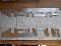 |
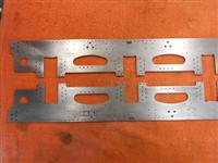
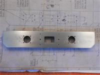
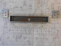
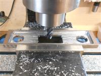
The tender frames have been made from guillotined pieces
of 3mm mild steel plate and were marked out by hand and all the cutaways
made with hacksaw and files. Because I didn't have my larger mill at the
time, all the original holes have also been marked out by hand or spotted
through the various components. The half-ovals were chain-drilled first,
followed by removing with a cold chisel and filing the shape to finish,
and the large hole at the rear of the frames was made using a hole saw.
Because most things are dimensioned to fit inside the frames, I kept these
dimensions and compensated for the thinner frame material (two lots of seven
thou) by making the horns a little wider. |
 |
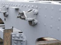 |
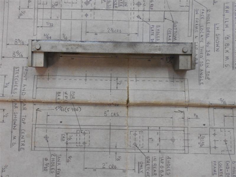
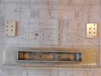
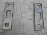
Looking at photos of the prototype, there
is a row of rivets that appears to run the full length of each frame just
below the sole plate. By counting rivets between the spring hangers, and
using the drawing dimensions between hangers, I was able to calculate the
spacing. The frames were set up on the new mill to add this detail and a
series of 1/16" holes drilled between the water filter and the rear steps.
The water feed pipe hides any rivets that may be towards the front and have
not been drilled. The picture to the left has been modified from one of
the Nigel Fraser
Ker photos. |
 |
A further detail I have chosen to incorporate are the
rivets for the rearmost top frame stretcher which is a series of twelve
holes, also in 1/16". The front stretcher is behind the filter box so wouldn't
be seen and not worth copying. The final detail I have added is the triangular-shaped
bracket directly above the centre spring and is cosmetic only. After removing
from the mill, all the holes were countersunk on the rear. The dummy rivets
were then fitted and hammered flat at the back, followed by dressing back
to flush, particularly in the area of the top stretchers. The triangular
brackets were also fixed and the frames are now ready for priming. |
 |
| 2. Front Beam |
|
|
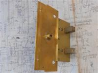
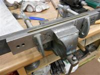
| The drawing shows the leading beam as a two-part
assembly with 1" x 1/2" x 1/16" channel behind the buffer plate, riveted
together. I had a short length of 1" x 10swg box section available and made
my own channel from this, whilst the buffer plate was cut from 3mm mild
steel sheet. The drawing also calls for the frame-mounting plates to be
silver soldered to the ends of the channel but I felt that some form of
mechanical fixing was also required and made a pair of angles to fit in
the ends of the channel and riveted to the buffer plate. I started by sawing
the box section longways to produce the channel, dressing the sawn edges
and milling the ends square and to finish length. The two angle pieces for
the ends of the channel were cut from the waste and the holes for the rivets
marked out and drilled. Next, I marked out and drilled the twelve rivet
holes in the front plate, countersinking quite deep, and all the bolt holes
for the bufferstocks and the pivot block. On the channel, I marked out one
rivet hole at each end and then riveted all the parts together, remembering
to include the angles. Now, it was easy to hold the channel in a machine
vice and spot through all the other rivet holes, finishing off by setting
all the rivets and filing the front face flush. They can just be seen in
the photo although this was taken later because I hadn't put the larger
holes in at this stage. All the other small holes were drilled through at
this stage also. |
 |
 |
The bufferstock location holes were made next, followed
by the drawbar slot which I stitch-drilled and chopped out, then filed to
size. I didn't have my larger mill then or I would have cut the hole with
a small slot drill. All the holes that needed threads were done at this
stage and care was taken with the pivot block holes as four of them foul
the channel behind. The reason for this is because the pivot block on the
loco has the mounting holes in a different position to the tender but I
had made mine both the same and had to modify the tender dimensions to suit.
The end plates were made from offcuts of the 3mm mild steel sheet. The two
forward holes were drilled 6BA clear and the four rearward holes drilled
and tapped 6BA. After drilling and tapping the angled ends of the channel,
I was able to bolt the end plates on prior to soldering. The two front screws
go through the frames and the end plates, screwing to the riveted angle
pieces, thus providing my mechanical fixing. |
 |
| 3. Forward Buffers |
|
|
 |
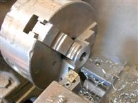
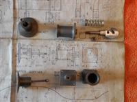
The buffer housings on the leading beam of the tender
are drawn as a fabrication silver-soldered together but I found it easier
to make mine from solid. There is little need for accuracy required here
other than a nice sliding fit of the buffer in the tube. Because my 3-jaw
chuck accepts 1.3/16" dia material in the bore I cut a 4.3/8" length of
EN1A, enough for two housing plus parting and facing. With half of the material
hanging out of the chuck, I faced off the bar and then turned the O/D down
to 0.650" for the 2" length shown. The bar was then reversed in the chuck,
shoulder up against the jaw face and the operations repeated, followed by
parting into two components. Leaving the first one in the chuck, I drilled
a 31/64" diameter hole to within 1/8" of the bottom, taking advantage of
the flange to prevent the material moving. The hole was then reamed 1/2"
diameter as deep as possible and the front faced to leave a flange thickness
of 1/16". This was repeated for the second one. |
 |
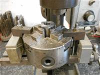 |
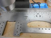
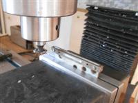
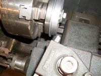
A small chuck was set up on the table of the Cowells
to enable machining of the square flanges, setting the centre as the zero
datum and milling an equal distance out from centre for each side. The four
mounting holes were centre-drilled at the same time but drilling was done
free-hand on the pillar drill as the Cowells doesn't have the headroom for
drilling. As you can see, it's a bit cramped on the mill table. The corner
radii were done freehand on the linisher and with files. The retaining slot
was made by holding the workpiece in a small machine vice and milling with
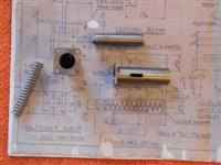
a 1/8" diameter slot drill. The retaining pin is yet to be made. The plungers,
or buffers, were made from 1/2" diameter EN1A. The hole for the spring was
drilled first and the O/D polished with emery to give a nice sliding fit
in the buffer housing. They were than reversed in the chuck and the front
form created by turning the shoulder and using a form tool to create the
radius. |
 |
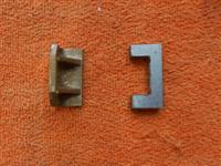
| 4. Pivot Block |
|
|
 |
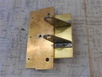
The pivot block was covered on Drawing 2 as
part of the loco rear beam but is included here for completeness. For anyone
making Britannia to this set of plans, the mounting holes are different
on the loco compared to the tender and causes a problem if made to the loco
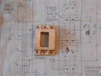
dimensions. The central stand-off bracket, or pivot block, is a fairly rough
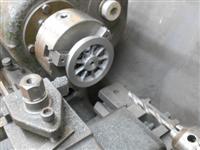
gunmetal casting and a little thought went into the machining sequence.
Because the casting sprues were so prominent, I decided to mount the pivot
block on a small angle plate, setting the side square to the table, and
milled the top edge with my small flycutter until cleaned up. Now that I
had one clean face to work from, all further work was done in the milling
vice, starting with the bottom face and then some more off the top to get
the webs and drawbar slot balanced. |
 |
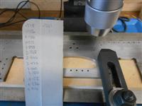
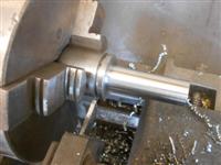
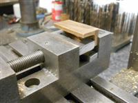
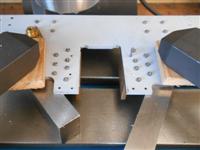
The next job was to face the back to the nominal size.
To get it level, I set four screws into the tender front beam (rear beam
of the loco in the picture) and adjusted them to the same height. This then
went into the bottom of the milling vice and the casting settled on top.
|
 |
 |
The back was then machined with a flycutter. There is
no size given on the drawing but scaling from the drawing, which is normally
inadvisable, worked out at about 1/8". It wont matter as long as I remember
to make the drawbar to suit, not just to drawing. The sides and the large
radius were dressed clean on the linisher - no particular size, just to
please the eye - and the mounting holes were marked out and drilled 6BA
clearance. To finish off, it was given a quick session in the shot blast
cabinet to make a good surface for painting. |
 |
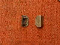
| 5. Rear Beam |
|
|
 |
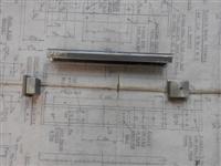
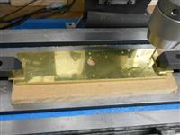
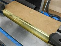
The rear beam has been made in a similar fashion to the
front beam, again using a section of 1" x 1/8" box section to create the
channel as well as my belt-and-braces angles at the ends of the channel.
This time, however, the channel is set level with the top of the buffer
plate and the plate is screwed on after other parts have been fixed. Because
of this, the angles were fixed in place first, and a very light skim given
to the ends to dress them square. As before, the side plates were made from
offcuts of 3mm MS sheet and bolted on before soldering together. All the
holes in the plate were marked out, centre-popped and drilled freehand.
The brass angle pieces were cut from stock material and drilled also. I
fixed all the dummy rivets first, followed by the angles and, finally, the
drawhook stregthening plate. |
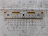 |
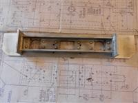
| The drawing calls for the buffer plate to
be riveted to the channel but I have chosen to use 6BA countersunk screws,
hence the deep countersinks. The screws will be filled prior to painting.
On the back of the buffer plate, all the rivet holes were countersunk and
the rivets have been hammered in and filed flat to enable fixing to the
channel. I managed to make a bit of a pig's ear of the buffer stock alignment
holes, as can be seen in the picture, having to file them over to get the
stocks to bolt on. It's not important, though, just annoying. The screw
holes are in the correct position. I am not going to cover the buffers and
buffer stocks because I made these on a Colchester Tornado CNC lathe eighteen
years ago and there is not much point in describing the process on here
even if I could remember it. |
 |
 |
I do recall that I made the stocks in a single operation from round bar,
leaving only the mounting holes and square shape to finish by hand. The
buffers were turned and parted off in a single operation, the parting
tool being used to get most of the way though, retracted and then following
the circular path needed to form the shape, just leaving a small pip to
linish off. Also in the picture is the drawhook which was made completely
freehand with a few drilled holes, a hacksaw and files. And then I remembered
that the tender buffers cannot be made to work in the same fashion as
the loco buffers because the frames clash perfectly with the centreline
of the buffers and a different means of retention was required! Therefore,
a 1/8" slot was milled in the underside of each stock for a distance of
3/8" and a 3mm threaded peg made that screwed into the buffer after assembly,
in the same manner as the tender-to-loco buffers.
|
| 6. Bottom Stretchers |
|
|
 |
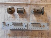
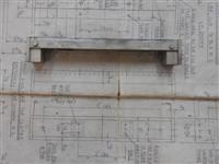
The drawing shows the two bottom stretchers as a fabrication,
made from 18 swg mild steel, but I have chosen to make mine from solid.
The drawing also shows them riveted into position but I am going to fit
mine with 8BA screws instead. To be any use, these need the length to be
reasonably accurate and I don't feel I could bend sheet steel to this level
of precision. Milling them to length is the obvious answer. Two pieces were
first sawn from 40mm x 10mm black steel and these were then cleaned up all
round on the mill, finishing at the exterior dimensions as per drawing.
Following this, the two circular and one rectangular relief sections were
milled away to leave a solid version of the stretchers. |
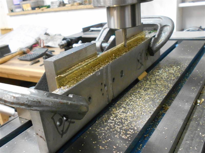
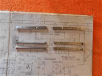
| Then it was time
to pocket mill the interior sections and this was done with a 10mm carbide
end mill, twenty thou depth per pass and full-width cutting around the periphery
before clearing the centre. All previous work had been done on the little
Cowells but I had my larger mill when it came to do this operation. As can
be seen, I have left the side wall thickness nearer to 1/16" rather than
the specified 0.048" but the ends are about 1/4" thick to allow for making
the fixing holes. When the milling was complete, the stretchers were clamped
to an angle plate and the holes drilled and tapped 8BA. Here are the two
finished articles ready for painting and assembly. |
 |
| 7. Top Stretchers |
|
|
 |
The top stretchers have been made in a similar fashion
to the leading and rear beams by using 1" square box section for the cross-member.
However, I made these as a fabricated item requiring no soldering because
they are just a spacer. To make the end pieces, I faced a pair of 1.1/2"
dia mild steel billets on the lathe, then milled them to the shape shown.
The holes in the ends of the channel were drilled 6BA clear and matching
tapped holes put into the blocks, which are a snug fit into the channel.
I also drilled the tank mounting bolt holes in the top of the stretchers
but had to redo them when I decided to change the position of the tank bolts
for ease of manufacture. |
 |
| 8. Horn Cheeks |
|
|
 |
The horn cheek castings come as a pair joined together
but I chose to separate mine and machine them separately. There was nothing
out of the ordinary in machining these, being held in a machine vice for
all operations. The only tip I can offer regarding these is the little clamping
piece I made up to help hold the work. With twelve cheeks to do, this came
in very useful and easy to use - beats juggling with other forms of blocks
or pads. When I mount the vice on the small Cowells mill table, the fixed
jaw is square to the table within a couple of tenths of a thou so I put
a double thickness of baking foil under the fixed-jaw end to create a tiny
deviation from the vertical for the fixed jaw, such that the finished components
were "toe-in" at the outer ends when mounted on the frames. |
 |
 |
Once all the milling was complete, the holes were drilled
and countersunk, and each cheek marked with it's location for strip-down
and re-assembly. It is usual to use rivets to fix the horn cheeks in place
and then final machine but I have fixed mine with cheats rivets - 8BA dome-head
screws without slots. This gave me the opportunity to adjust the cheeks
using a 1.1/4" square bar and feeler gauges, without the need to machine
them in situ. Once they were screwed firmly into place, two holes were drilled
through the frames and into the webs of each cheek and a pair of silver
steel dowel pins inserted. This should stop them moving in service since,
unlike the main locomotive horns, they are not subjected to a reciprocating
action. |
 |
| 9. Horn Stays |
|
|
 |
The horn stays were made from some 1/4" square mild steel,
cut to length and the rear milled away to create the required shape. Although
not shown on the drawing, I have also milled the fluting that is evident
on photos of the prototype using a small Woodruff cutter. A pair of tapped
holes were put into an offcut of mild steel sheet to allow bolting of the
components prior to machining. |
 |
| 10. Top Plate |
|
|
 |
The area behind the leading beam is taken up by a strange
ensemble of plates and spacers that provide support for the drawbar pin
supports, the brake and scoop bellcrank assemblies and also the upper platform
and deflection plate. The top plate, made from 16 swg brass sheet, sits
between the frames and is flush with the top. Soldered to the underside
of this is the upper drawbar pin support, made from 1/2" dia brass bar.
The hardest part of this component is deciphering which of the mish-mash
of dimensions on the drawing relate to this and which to the lower plates.
After making each of the items as per drawing I found it very awkward to
assemble the parts, wishing for a second pair of hands. Subsequently, I
made a modifications to make life easier which was to discard the lower
front spacer in favour of three brass bushes soldered to the underside of
the top plate since these cannot be seen once assembled. |
 |
| 11. Bottom Plates |
|
|
 |
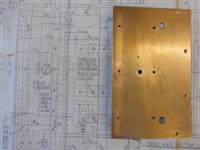
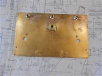
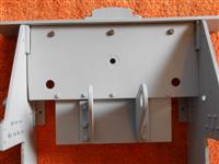
There are two bottom plates joined by a length of 7/32"
flat bar. The front one of these carries the lower drawbar pin support which,
like it's upper counterpart, is soldered to the plate. The lower one carries
the scoop and brake bellcrank brackets below, and a pair of spacers above
for connecting to the top plate. The drawing suggests riveting the two plates
together through the flat spacer bar but I have fixed mine with 8BA bolts
and nuts. The brake brackets are made from 3mm mild steel plate and are
bolted to the plate with the centre screws going into the 1/2" square spacers.
|
 |
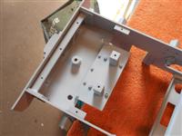 |
I'm not modelling the scoop and associated gear but it
can be added later if I change my mind. These two views are the lower plates
primed and in position. |
 |
| 12. Platform |
|
|
 |
The platform is made from 20 swg brass sheet. It was cut out with a hacksaw
and then filed to size prior to marking out the bending position. The
material was left a little long to assist with bending and the two notches
at the front were cut away. Bending was performed the old-fashioned way
of supporting between two hefty lumps of steel and gently peening over
with a mallet. The platform was then set up against angle plates on the
mill and the height of the platform lip machined to size.
|
 |
 |
I tried it laid flat and using the end of
a milling cutter but it was difficult to support the edge and stop it ringing
like a bell. Using the side of an endmill moves the cutting forces down
into the material, rather than at ninety degrees, and the lip becomes self-supporting.
The next operaion was drilling all the holes and the plate was clamped on
a piece of MDF, trued up and the holes made by using co-ordinate drilling. |
| 13. Deflection Plate |
|
|
| The deflection plate is also made from 20
swg brass and was prepared in much the same way as the platform. The holes
at the base of the deflection plate were drilled in a similar manner, the
tee slots on the table being deep enough to the allow the material to sit
nicely on the 12mm MDF and squared up against the edge of the tee slot. |
 |
| 14. Wheels |
|
|
 |
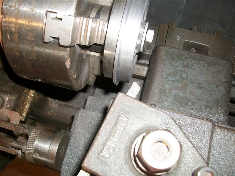
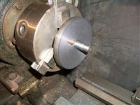
After a small amount of fettling to clean
up the spokes a little, each wheel was mounted in the independant four-jaw
chuck, front face inwards and holding on the tread, and adjusted until the
boss ran reasonably concentric. The back was then faced off till clear of
witnesses and a further ten thou taken. The bore was drilled 1/8" undersize,
followed by boring with a small boring bar to 1/64" undersize and finally
reamed to the correct size. The O/D of the wheel flange was also skimmed
to clean up but not to size. The wheels were then mounted in soft jaws on
the three-jaw chuck and the bosses faced to clean up followed by machining
the face of the wheels. The object here was to try ang get the correct look
of the wheel-rim against the spokes without removing too much metal and
leaving the wheel thickness undersize. Once I was happy with this, I then
continued facing off the boss to the correct distance from the rim. The
tyre was then turned to about sixty thou above finished size to get it concentric
for holding on the next operation. I'm missing a couple of pictures here,
and I've checked all my backups, but a wheel in a chuck doesn't look like
much else so no great loss. The wheels were then reversed in the chuck and
the backs machined down to finished thickness. The O/D of the wheel-rim
was also skimmed to finished size and a radus filed onto the rear edge. |
 |
For the tender wheels only, I made a fixture which allowed
me to mount each wheel on a mandrel correctly sized to the axle holes, held
with a nut and washer, and with a driving pin to provide positive drive
through the spokes. A piece of tool steel was ground to produce the root
radius of the tyre and flange and the compound slide set over to two degrees.
Using this tool, itself set over to the correct five degree angle, the flange
was faced off to the correct thickness and the saddle was locked at this
position. The compound slide was then retracted and the tyre machined to
the correct angle using the compound slide instead of the carriage. Care
was taken near the end of each cut to get a nice blend with the root of
the flange. Once finished, I filed the radius to the edge of the flange
and the wheels were complete except for further fettling of the spokes. |
 |
| 15. Next Item... |
|
|
| |
|
|