| Drawing 18 - Cab and Details
|
| 1. Cab Floor Supports |
|
|
 |
The five cab floor supports were made from 1.1mm mild
steel sheet, bent to create the angle-iron shape and the end folded in and
silver-soldered. I made mine at right-angles to the spar rather then angled
and filed the anchor blocks on the boiler backhead to suit. I managed to
get one of the blocks in the wrong place and had to modify the spar to suit.
After drilling the various holes and milling the slots, they were pickled
in citric acid to remove the galvanising to allow the primer to adhere properly.
After assembling the floor and cab, it became obvious that the holes for
the handrails were incorrectly dimensioned on the drawing and will need
to be redone. |
 |
| 2. Cab Floor |
|
|
| The cab floor was marked out then finished
to shape with hacksaw and files. Holes for the fixing screws were marked
out, drilled and countersunk to accept 8BA c/sunk screws and finally spotted
through to the support brackets. The timber floor boards will hide most
of these. Other holes have been drilled as required including some tapped
holes for the back wall. The angles to the sides are for fixing the side
sheets to and there are a pair of small brackets for the angled walls at
the front. |
 |
| 3. Cab Sides |
|
|
 |
The cab sides have been made from the same material as
all the other cab parts, scaling from the drawing where neccessary. To get
the curved shape where the cabside meets the running boards, I set them
up on the mill and drilled two 1/2" dia holes and finished with a 16mm end
mill. The rivet holes were equally spaced around the perimeter, the ones
at the base of the cab being for dummy rivets in the prototypical position
rather that that specified on the drawing. I'm also fixing my cabsides using
full-length brass angle instead of the method drawn. The four corners of
the windows were also drilled prior to cutting out with a 1/8" dia end mill.
In both cases, I'm doing both sides at once, clamped together. |
 |
 |
Holes were also drilled for the windows runners, the windshields
and the top gutters. A locating strip was also made which screws to the
top of the cabside, held by two 8BA c/sunk screws, for positioning the roof.
These screws are hidden by the gutter. Finally, 3/32" half-round beading
was soft-soldered to make the window frames. I made them as four sections
per window, clamping each section in turn, drilling three 1.1mm holes and
fixing with fine brass nails. The sections were then gently eased to the
exact position required, well fluxed and soldered. The window on the left
needs a little more work but shows the finished job reasonably well. |
 |
| 4. Cab Rear Wall |
|
|
 |
Cut and bent in the same way as all the other
bits but included here for completeness. The angle brackets are home-made
from offcuts of the same steel sheet and milled to 5/16" wide. They are
fixed to the wall with 1/16" rivets and screwed to the floor with 6BA bolts.
The shape was formed using the plan-view on the drawing as a template. |
| 5. Cab Roof |
|
|
 |
I've made the main roof section in three parts, mainly
because it suited the material I had to hand. The two sides are mirror-images
of each other and the shapes were cut before bending. The curvature of the
roof has not been formed yet. Another offcut was shaped to give an approximate
outline of the front facia of the cab, mainly to give the correct height
above the firebox. This will be replaced later on with a more accurate piece. |
 |
 |
The centre piece was then made to fit the gap, much easier
than trying to get a single piece bent accurately in one go. Half-inch wide
joining strips are fitted below and held with 8BA c/s screws and a removeable
panel will be made to slide into the gap. The roof curve was formed around
a gas cylinder. Finally, the gutter strips were fitted and the roof section
primed. |
 |
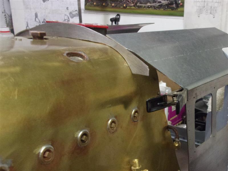
| 6. Cab Fronts |
|
|
 |
Getting the angled front walls of the cab required a lot
of work with cardboard until I was confident enough to cut metal, both sides
being very slightly different. A lot of trial and error and a whole cornflakes
box needed. The two fronts were cut after marking round the template and
individually filed to fit. Then they were covered with masking tape and
the windows marked out. The four corners were cut away with a slot drill
and the waste removed before finishing with files and sanding drums. The
rivet holes were drilled using the DRO for accurate spacing and the hole
at the bottom is for an 8BA countersunk screw, fixing to the tiny bracket
at the front of the cab floor. Instead of using half-round beading, I am
using 16 swg brass offcuts to make the window frames which should, hopefully,
disguise the error in one of the lower corners (I filed them out too much). |
 |
 |
The outside of the brass was worked until they were correct
for the outside form of the windows, then very carefully postioned and held
with clamps. Flux was liberally applied, lengths of soft solder cut and
laid against the joins and heat applied slowly and carefully from below.
The clamps lifted the assembly enough for the flame to go underneath. The
windows were then chain-drilled from the back and the windows filed to shape.
One of the frames was a little out of position so the assembly was gently
reheated and the frame nudged over slightly to get it looking symmetrical.
I shall round the edges off a little just prior to painting. |
 |
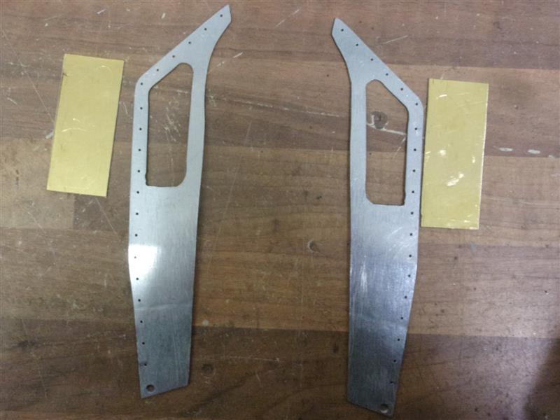
| 7. Cab Rear Screens |
|
|
 |
The rear screen walls are different on either side, the
driver's one being full-height with a window set into it. I am making both
of mine to the pattern of the fireman's side for ease of access when driving.
Once again, cardboard templates were made to fit the roof shape and two
panels cut from 1.1mm galvanised steel sheet. I also made the angled pieces
that support the two doors. The screen walls have dummy rivets for most
of their height with a pair of 10BA bolts used to hold each of the angles.
The angles on the upper sections support the roof. I haven't yet decided
whether or not to fit the half-round beading. |
 |
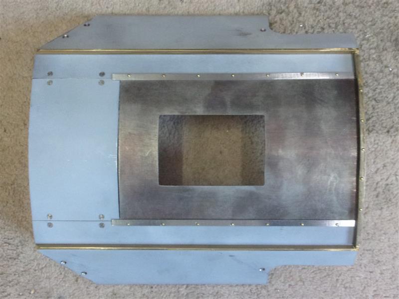
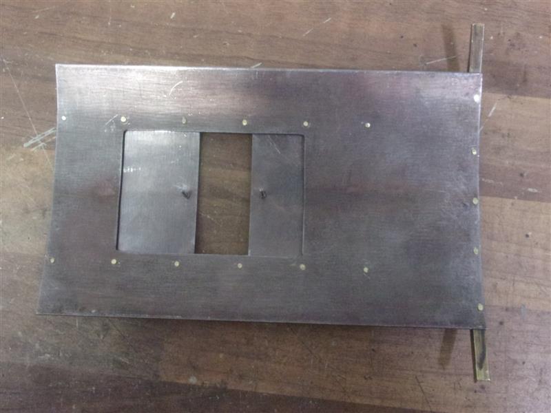
| 8. Sliding Roof |
|
|
 |
The removeable roof section also contains the two sliding
panels that are, I think, fitted on all BR standards. Four thin strips of
steel, 5/16" wide, have been placed two either side and fixed with 3/64"
brass rivets to act as the guide rails. These were milled and drilled on
a special fixture (described in the tools section). The sliding section
was bent to shape and the rear gutter strip fitted. This extends across
the fixed roof section and butts up to the side gutters, making it one less
edge to catch a wrist on when driving and firing. The two pictures show
the removeable section partially opened and fully closed. |
 |
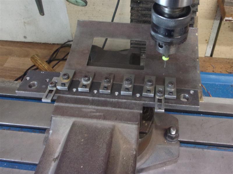
 |
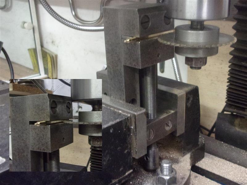
The rails for the sliding panels are shown as a milled
section but I have built mine up using three layers of the 45 thou steel
with a narrower section in the middle of the sandwich. The holes are at
1" centres and the edge of the rails are at the edge of the cutaway. Because
the roof was already bent, the fixture I made for milling the strips came
in handy for drilling the holes. It was mounted into a tiliting vice to
bring the drilling line level with the table. |
 |
 |
I still need to make the handles for the sliding panels
and these will be fixed with 10BA rivet screws. This will allow them to
be dismantled at a later date, if neccessary. The final picture shows the
whole thing assembled and ready for primer painting. |
 |
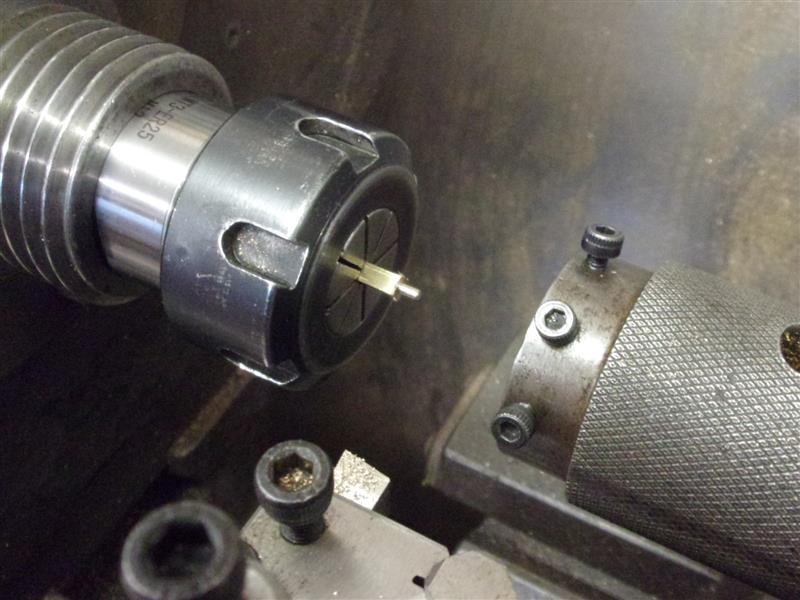
| 9. Windshields |
|
|
 |
The windshields on either side of the cab have a top and
bottom pivot block, the support bar and a perspex window. The blocks were
made from 1/8" square brass, a 1/8" length turned to 0.067" dia, threaded
10BA then parted off 1/4" overall length. A 1.7mm cross-hole was drilled
in the body of the blocks for holding the support bar. The support bar was
machined from 1/8" dia brass rod, with a spigot turned on each end 1/16"
diameter by 1/8" long. Over on the mill, a slot was cut with a slitting
saw to squeeeze the perspex into. Although the drawing shows a 1/16" depth
of slot, this would wreck the pivots on each end and a first pass was made
at thirty thou depth followed by a plunge beyond the spigot to seventy five
thou depth, along to the end and out again before hitting the spigot. |
 |
 |
The perspex was marked out to the shape of the windshield,
then cut out and filed to finished shape. A section was filed away at each
end to clear the run-out of the groove and the perspex pressed into the
slot. They are a tight fit and don't require any adhesive. I have made my
windows 1/4" shorter than the drawing, more closely sized to the prototype,
and the windshields are also a quarter-inch shorter than drawn. The final
picture shows the driver's side in postition. |
 |
| 10. Cab Handrails |
|
|
 |
There was some surplus 1/8" dia stainless steel tube in
the stock drawer and this was used to form the cab handrails. Because of
the three bends in them, I decided to do them in two sections with the join
hidden in the doorway stanchions. Using tube meant I could easily drill
and tap the lower section so that an 8BA screw could be used to fix them
to the platform support. For the top, I made some 5/16" long blocks from
1/4" square mild steel with a 1/8" dia hole drilled for a 1/8" depth. These
were then cross-drilled and tapped 10BA and bolted to the cab roof. The
drawing shows a soldered fixing point but this is easier. I had to remake
my platform supports because the holes were in the wrong place, though. |
 |
| 11. Next item... |
|
|
| |
|
|