| Drawing 13 - Boiler Fittings
|
| 1. Safety Valves |
|
|
 |
I turned the outside form first, including the diameter
for the hexagon section, then drilled the 3/16" diameter hole through. To
make the ball-seat and tunnel I mounted an 8mm end mill in one of the toolpost
carriers, centred it off and plunged to depth. I find this easier and more
accurate than messing around with cutters in the tailstock. The top part
was then bored to size and depth, lightly chamfered and tapped 1/2" x 40
tpi. Then it was parted off to length and the second one made. |
 |
 |
Next I set up a button die and tapped a one-inch length
section of brass bar to be used for the adjusters. I also made a mandrel
to screw the valves onto for milling the hex and for making the external
threads on the valves. The tapped valves were used as the gauge. The hex
was milled using the rotary table to index round, it's only a spanner flat
and half a degree or so out matters not at all. |
 |
 |
The mandrel was then set up in the lathe and the external
1/2" x 40 thread cut. I just run the lathe at it's lowest speed, hold the
die holder on it's guide, start cutting and wait till it hits the front
and let go. I've put a root-diameter undercut at the back of the thread
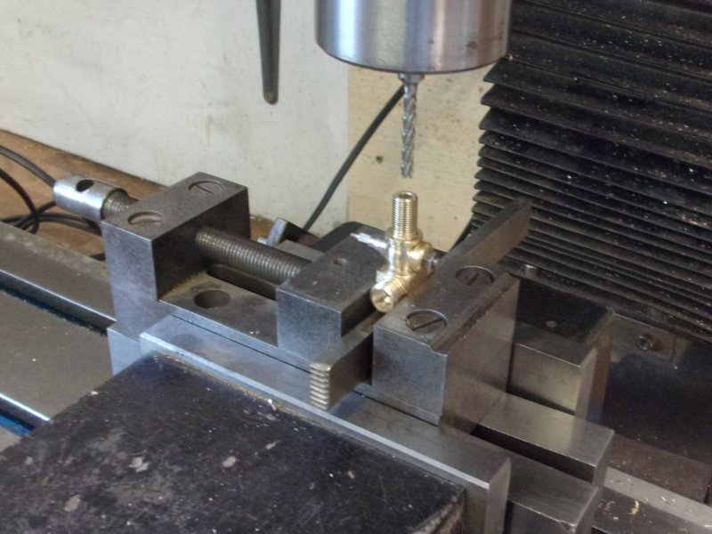
to assist seating of the valve body. To make the adjusters, I stood the
threaded rod upright in a chuck on the mill and drilled all the holes using
co-ordinate drilling. I made the 1/16" dia holes about 3/4" deep |
 |
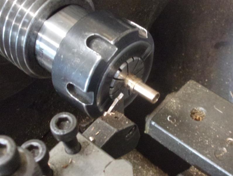
| The rod was then returned to the lathe and the two adjusters
parted off. The bit left over was turned down to below root diameter and
three panel pins loctited into the holes. This will become the adjusting
spanner, I just have to drill a small cross-hole. |
 |
| 2. Regulator Body |
updated 04/07/2021 - see below |
|
 |
The regulator block is an interesting part to make although
somewhat complicated. Although others have opted for simpler off-the-shelf
stainless steel ball valves, I prefer the challenge of machining the drawn
item. I started with three lumps of brass which I machined all over to the
major dimensions of each part. They are the bottom cover, the main valve
box and the steam chest (not stricty correct but suits the circumstance).
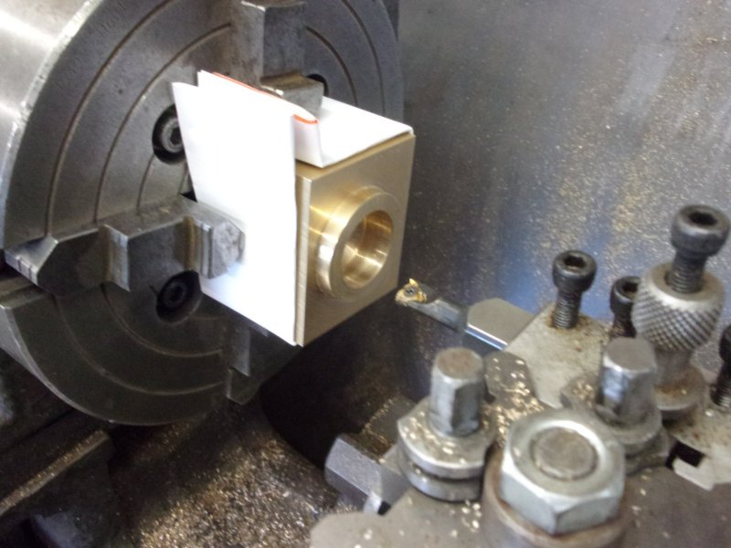
Carrying on with the main block, this was loaded to the 4-jaw chuck and
the boss that connects to the steam collector turned to size. The bore for
the large thread was next and then screwcut, pulling the chuck round by
hand because of the blind bore. The steam collector bush was used as a gauge. |
 |
 |
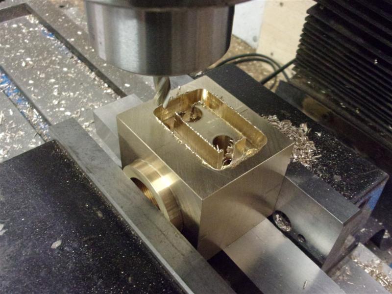
Over on the mill, the two valve holes were tackled next.
The threaded portions at the top of each were drilled and tapped first,
followed by drilling and reaming the respective bores. The block was then
upended and the hollow for the actuating mechanism milled away. I used a
1/4" dia cutter to trace a path round the outside, fifty thou depths of
cut until full depth was reached. |
 |
 |
After the inside was cleared away, the holes for the bottom
cover plate were drilled and tapped using co-ordinate positioning with the
DRO. The two holes for the actuating spindle were next, starting with the
larger one, drilling and tapping to size. Without moving the table, a long-series
spotting drill was then used to start the hole on the opposite side, ensuring
it stayed in line with the first hole. |
 |
 |
The rear of the block was next, drilling and tapping the
fixing holes for the steam chest and drilling the short hole where the delivery
bores meet. This picture was taken later, I forgot at the time. Now is where
it gets interesting. The bores from the steam collector to the valves, and
from the valves to the steam chest, are compound angles. After working out
the respective angles of each bore, the block was loaded to my tilting vice
with angle gauges underneath the block to set the other angle. |
 |
 |
It's practically impossible to position this with any
degree of accuracy - too many variables including depth of the hole etc
- and was mainly set up by eye. There is a good margin of error, however,
and this turned out quite well. The opposite side was done in a similar
way. The hole for the whistle feed was done last and needed careful positioning
to ensure it missed the other steam channels. This is the finished block. |
 |
 |
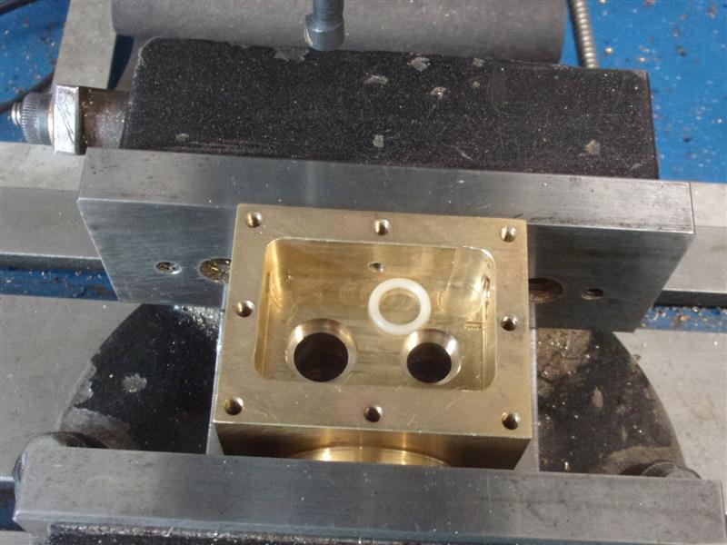
Updated - during testing, I was getting some leaking from
the bottom of the regulator block, getting past the valve stems into the
actuating chamber below. For this, I machined a pair of "O" ring seats into
the bottom of the block. I also needed a cover plate to hold them in place
and this was duly made from 16 swg brass sheet. The two outer holes were
opened up in stages to the correct diameter and a countersunk clearance
hole made in the middle for a 6BA screw. |
 |
 |
The block went back into the vice and a pocket milled
for the cover plate plus a 6BA fixing hole drilled and tapped. The valve
stem holes need to be bang in line and these were reamed to size with the
plate in position, done from the top side, this dismantled and the "O" rings
fitted. With the plate in position, I can now rebuild the operating levers.
If it leaks after this, I will probably bin the whole thing and make something
completely different. To be honest, this block is poorly designed with multiple
opportunities to leak. Fun to make, though. |
 |
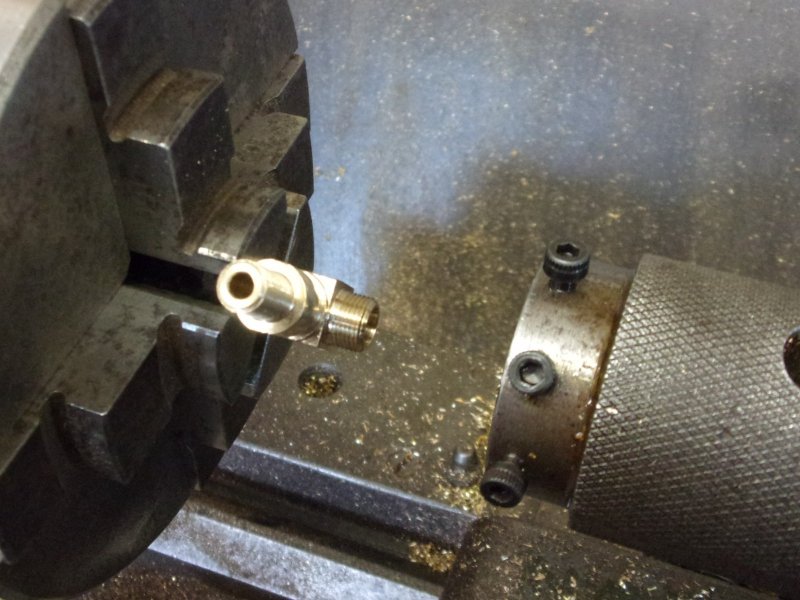
| 2-1. Regulator Body (replaced 26/07/2021) |
|
 |
This regulator block has still been giving
me grief, this time failing to seal at the valves. I have remade the valves
with slightly longer stems for a better fit in the guides, polished and
reseated the angular contact faces on numerous occasions, changed the springs,
removed the springs, removed the actuating mechanism and recut the seats.
Even a damn good thump with a hammer has failed to achieve a seal so, after
wasting the best part of twenty hours, I have now abandoned this block completely.
I have also deliberately destroyed it so that I am not tempted to have "just
one more go" as I know it will end in failure. High blood pressure I can
do without! Plan "B" is to replace it with a stainless steel ball valve
that is gas-rated. However, I have had to make various adaptors to allow
them to fit and still keep my superheater assembly. I started with a choice
of two styles to see what I could adapt the easiest. |
 |
The larger one looked promising but it was extremely stiff
and a little to bulky for the available space. Using the small one, I trimmed
it down in length and turned a spigot on one end. I had the copper cover
plate that I used to test the superheaters but it had 4BA clear fixing holes.
I made a new one with 4BA tapped holes to fix to the steam chest because,
with the limited space, getting nuts round the back would be extremely difficult.
With it all fitted together, this is how it looks. I've had it under pressure
for a quarter-hour and also used the valve to test the ease of movement
and I'm very pleased with the outcome.. |
 |
| 3. Regulator Steam Chest |
|
 |
Both valves feed steam to this space which
I shall call the regulator steam chest. From here, two pipes go to the wet
header. After machining to size all round, the workpiece was hollowed out
in similar fashion to the regulator block. The fixing holes were drilled
using co-ordinate positioning and the two holes for the pipes drilled ready
for silver-soldering those in. The bottom cover was made next, again milling
all round and drilled 4BA clear. |
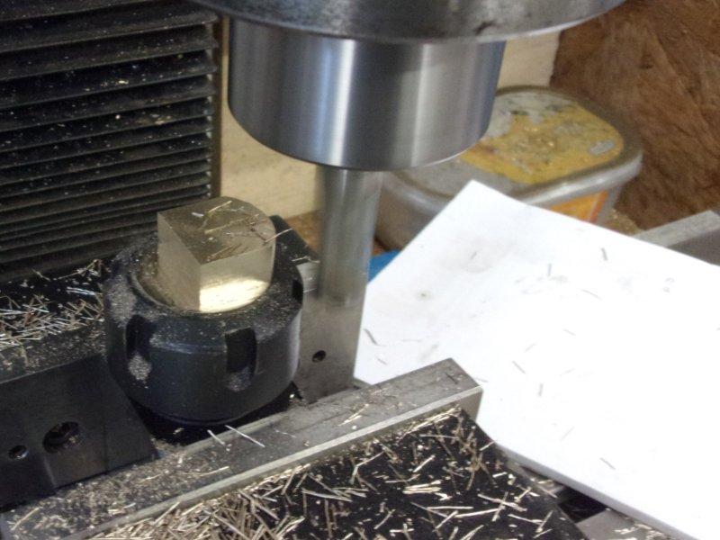
| 4. Regulator Top Plugs |
|
 |
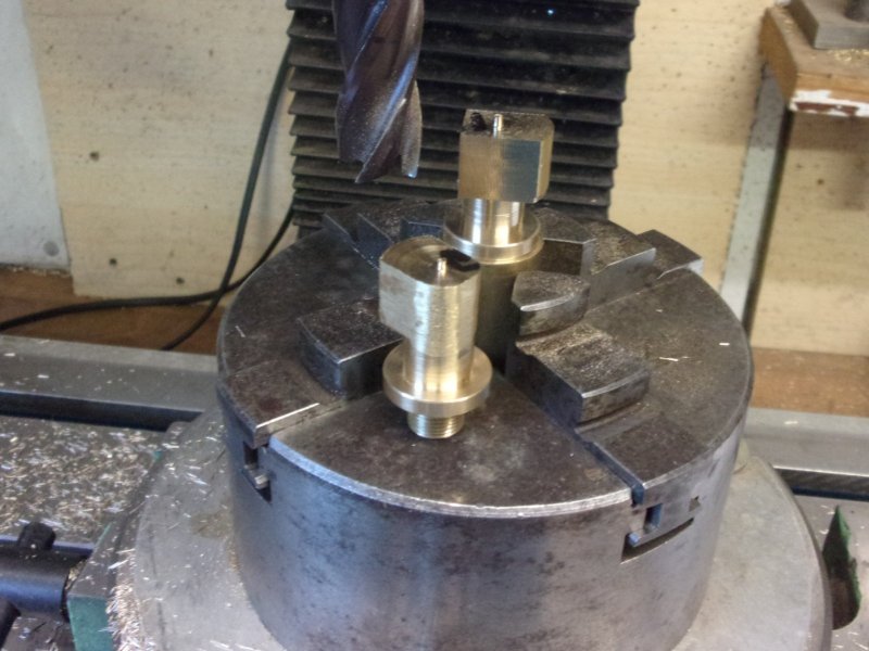
The regulator top plugs were made from 3/4" dia. brass
stock, machining the front end in one go and parting off to length. Rather
than the 9/16" x 26 thread that was specified, I have made mine M14 x 1
because I have a matching tap and die. The regulator block was used as a
milling fixture, screwing each plug in turn and tightening with mole grips.
After finding centre and setting 0,0 on the DRO the square was milled to
equal x-y co-ordinates, working full-depth and 25 thou steps. After the
first pass, the plugs were tightened with a spanner before continuing. |
 |
 |
However, these plugs may need to come out
with everything in situ and I was struggling to get a spanner in there.
I decided to remake the plugs with a 10mm hexagon head instead to allow
access with a box or ring spanner. I also skimmed a little more off the
o/d of the plug to clear the cutaway in the smokebox. |
| 5. Regulator Accessories |
Modified 21/01/2021, see Assembly page |
|
 |
I haven't described the various small parts
of the regulator mechanism because they are all easily-made parts. I did
make the spindle from 3/16" dia stock bar and fit a collar and pin rather
than turn down a long length of stainless rod. The operating arms were milled
from 3/8" square brass, drilled and reamed 3/16" and the rest of the work
was filing and linishing. I've left the web thicker on one side, tapped
them M3 for grub screws and assembled them screws down. Valves to follow
later when the material arrives. |
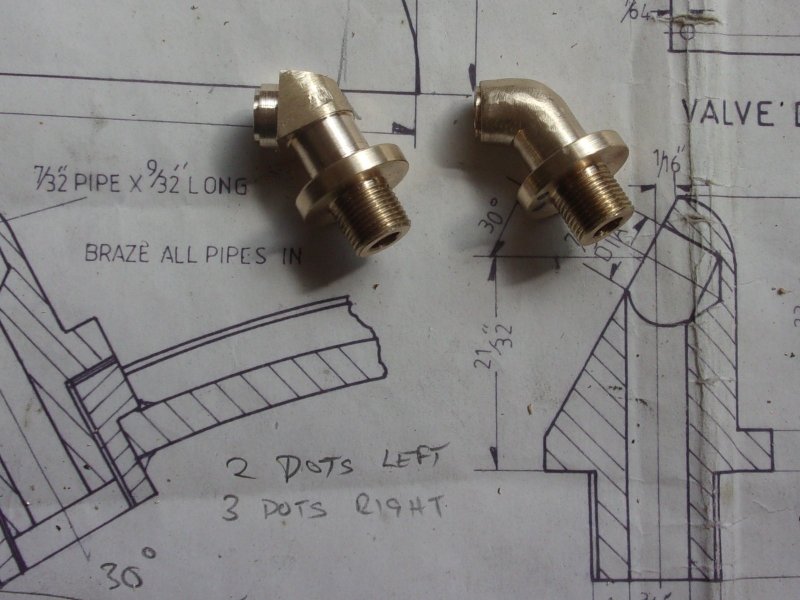
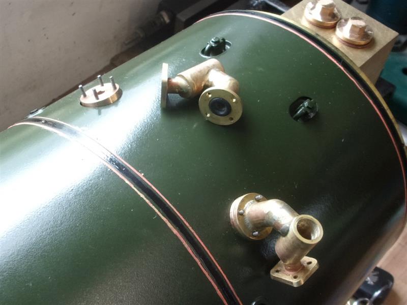
| 6. Top Feed Clacks |
|
|
 |
The drawing shows functional but not very prototypical
top feed clacks so I have tried to compromise between the very simple drawing
and the very pretty castings from Adam Cro and others. I started by making
the outlet section of the clacks that screw into the boiler bushes. A length
of 3/4" dia brass was turned to 11/16" outside diameter and the front turned
to 3/8" diameter by 3/8" long. This was threaded 3/8" x 32 tpi using a button
die. A 3/16" diameter blind hole was drilled 1" deep, and multiple plunge
cuts were made in the rear section with the parting tool to reduce the diameter
to 3/8" by about 5/16" long. The component was parted off 1.1/4" long and
numbered. Each part was screwed into it's respective boiler bush and tightened
down onto a fibre washer, then marked to show the front. Work now transferred
to the mill. Using a previously-made hollow mandrel, the parts were screwed
in and tightened with mole grips. Three sides of the top part were milled
to leave the shape shown here and the back part was rounded off on the linisher
to match the turned diameter. |
 |
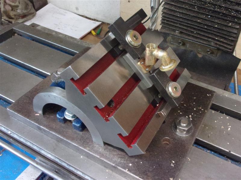
 |
Next, the mandrel was held in a vice at thirty degrees
to the horizontal to allow machining of the top and front face of the outlet
pipe. The top was machined first, aiming for a cleaned-up length of about
7/16" followed by the front until it just reached the first machining. |
 |
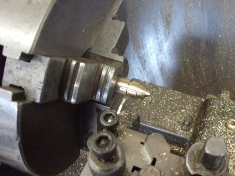
 |
To the left is a view from a different angle. The mill
was then centered on a point 3/16" in from the end and a 3/16" hole drilled
to meet the hole up the centre of the part. This was followed by turning
a 1/4" dia external spigot for 1/32" deep using a boring head with a home-made
cutter in it. The boring head was then adjusted to machine a 3/8" dia down
the neck until it met the main stem diameter. |
 |
 |
The rest of the work on these parts were with files and
sanding drums. After soldering, they can be cleaned up some more. The next
component was the pipe and flange fot the inlet of the topfeed. This was
machined from a piece of 5/8" square brass, turning the pipe section 1/4"
diameter, drilling a 3/16" diameter hole and parting off to length. |
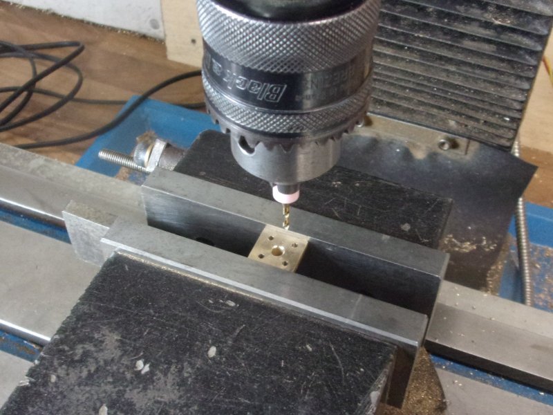
 |
 |
The four bolt holes in the flange were drilled on the
mill on a 17/32" PCD using co-ordinate positioning. No centre drill, the
PCB drills are rigid enough to start true as long as the chuck runs true.
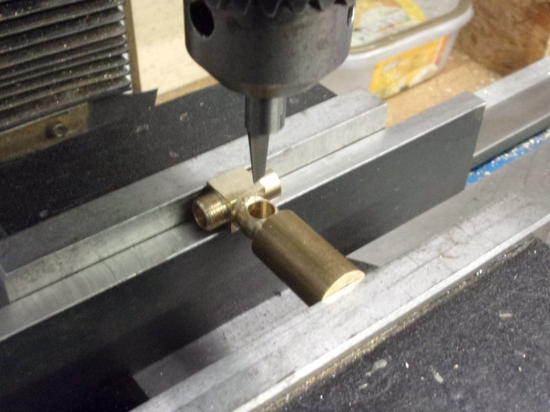
The third part, the clack body, was made next, turning 1/2" diameter brass
to 7/16" diameter, drilling the 9/32" hole with a spotface drill to form
the ball seat and continuing with a 3/16" drill to 7/8" deep. The front
was tapped 5/16" x 40 tpi and then the component was parted off 7/8" long.
These were than taken to the mill and the seat for the outlet pipe machined.
This is spotfaced with a 10mm slot drill and counterbored with a 1/4" slot
drill by thirty thou deep, finishing by drilling through 3/16"" diameter. |
 |
 |
The bottom needs to have an access hole at 45 degrees
for the inlet pipe and a simple locating jig was made from some MDF with
a 3/16" dia pin set in. No need for a fancy fixture here. Once set in the
vice, a 1/4" slot drill was lined up with the corner by eye and plunged
into the work until a full witness was obtained. I managed to mess up the
first one, crushing it in the vice but, because I nearly always make a spare
where parts need multiple operations, I took the opportunity to cut the
first one in half and see where the slot drill met the 3/16" hole. I also
screwed a plug into subsequent clacks for a bit of protection. |
 |
 |
This showed that I could safely shorten the clack by another
1/8" which looks more prototypical. After facing off, they were returned
to the mill and the angled hole completed. Then it was time to solder the
three parts together. The pipe and flange were soldered to the body first
using higher-temperature 40% silver. This was straightforward to hold and
solder but the next bit needed a more complicated arrangement. There is
a ring of 55% silver solder around the outlet pipe and, once the flux started
to melt. all heat was directed to the inside of the clack body. This drew
the solder down perfectly into the joint. |
 |
 |
The fourth and final part was the screwed plug at the
top of the clack. This was turned complete from 3/8" diameter brass. The
plugs were screwed into a hexagon mandrel and the flats machined on the
mill. |
 |
 |
The mandrel and component were returned to the lathe and
the domed head formed on the top of the plug. The rest was just filing and
polishing. I'm quite pleased with the outcome, not as pretty as Adam's super-detailed
castings but a bit better that what was drawn. Although the drawing calls
for brass for the majority of boiler fittings, my colleague Adam suggests
I would have benefitted from using bronze to reduce the risk of embrittlement
through de-zincification. |
 |
| Top feed clacks cont. |
updated 04/07/2021 |
|
 |
I've been chasing down some leaky boiler fittings
and one of the first was the topfeed clacks. I was using a spacer to bring
them above the cleading and I was getting some weeping at the thread. By
the time I tightened them enough to stop the weeping the orientation was
a long way out. I've remade them using a threaded spacer to get above the
cleading and 10BA studs to hold the fittings and using an "O" ring to seal.
The plugs were made from Colphos and the clacks from some unknown bronze.
I broached a hexagon into the top of the plugs using a cut-down 5mm Allen
key and tightened them in fully before marking the positions of the studs. |
 |
After silver-soldering the parts of the clacks together,
I needed to remake the seats and made a little fixture to help. It's a good
job I did because after a quite few recuts I still couldn't get a good seat
with a silicon nitride ball. The shape of the clack makes it nigh on impossible
to press a ball into the seat. Eventually, I gave up and used 1/4" nitrile
balls instead and had a perfect seal. |
 |
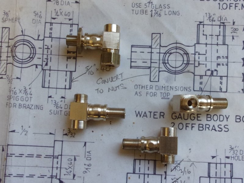
| 7. Water Level Gauges |
modified 07/07/2021, see below |
|
 |
There are quite a few parts that need to be made and brought
together to make the boiler water level gauges or 3-cock gauges as they
are sometimes known. The drawing suggests making the main bodies as two
parts and brazing together but I've chosen to make them in one piece from
bronze. Making two back-to-back from the same billet gave me a bigger section
to hold on for the first operation. Here, I've turned and threaded the part
that screws into the boiler and also drilled a blind hole for the water
passage, being careful to get the depth spot-on. The hand-ground form tool
for the globe section is also on view. Rather than the shoulder that's drawn,
I will be using thin locknuts instead. |
 |
 |
After both were machined, the billets were sawn in half
and then held in soft jaws to machine the back to the finished size of 3/8".
I've made this as close to size as I can to help a future operation. Moving
to the mill, the were machined down to 3/8" wide by 25/32" long. I deliberately
left a shoulder after the globe part so that I could hold it in a collet.
This is a square-sided ER25 collet block with ground faces all round. |
 |
 |
Once again, I made sure that the 3/8" dimension was accurate
so that I could hold the work in a self-centering 4-jaw chuck. The witness
left near the collet is about five thou thick. After filing away the flash,
this is what I was left with. |
 |
 |
Back to the lathe and with the S/C 4-jaw chuck mounted,
the reason for getting those 3/8" dimensions accurate is clear. Holding
on one section, the O/D was turned first and the 1/4" x 40 tpi hole drilled
and tapped. This was extended with a 1/8" drill until it broke into the
cross-hole at the half-way point. The parts were then reversed in the chuck
and the external thread for the gauge glass nut made. |
 |
 |
As can be seen on the drawing, the only difference between
the top and bottom fittings is the through-hole, the upper one allowing
the glass to be inserted from the top and rested in the lower fitting. The
holes were drilled to suit, two of each. The spindles for the 3-cock gauges
were made from surplus M8 stainless steel bolts and I wish I hadn't bothered
- tough as old boots! Another time, I will treat myself to some free-cutting
material. After sawing off the bolt heads and the threaded section, they
were held in a collet and the front-end section turned. The compound slide
was set round at 6 deg. for this so the tapered section was also machined
at this visit. |
 |
 |
I didn't go any further with these yet as I wanted to
make the reamer while the compound slide was still set. This was made from
some 5/16" silver steel, hardened and tempered. Next I drilled and reamed
the tapered bores in the valve bodies to match the taper on the spindles.
It's not so easy to control the depth when working with tapers and, since
I don't have a quill stop, I worked very precisely to the digital depth
gauge. I screwed them into a threaded bush to protect the ends from crushing. |
 |
 |
Then it was back to the spindles and get the squares milled
on. To turn the opposite end, I made a small carrier from brass with a matching
taper and a hollow back for a locknut. Twelve degrees inclusive is way above
the self-locking taper amount, usually taken to be about five or six degrees,
depending on surface finish. |
 |
 |
The rest of the turning was done in one visit using the
compound slide to index along for each shoulder. Not a very good picture,
unfortunately, the morning sun was shining strongly through the window.These
are the finished valve spindles with a modification that I've chosen to
make. They are about 1/8" longer and have an 8BA thread on the opposite
end for a handle retaining nut. |
 |
 |
I didn't bother to take pictures of making the gauge glass
nuts, locknuts or handles and I still have to finish the blowdown valve
at the bottom of each assembly but here is a picture of them ready to be
screwed into the boiler. Another job done was to mount the gauge glass valves
to get them square and measure for the linkages. I also cut the glass tube
to length and have loaded them into place. |
 |
 |
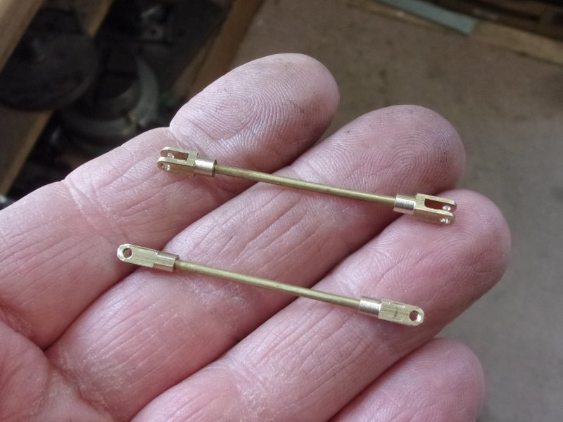
To make the top and bottom fittings to work in concert
a linking arm was made to operate both cocks simultaneously. Considering
the size of my machines, these are seriously small. Very little machining,
the slots being hacksawed and filed in the rod eyes. The handles for the
cocks were made from 1/4" x 1/8" brass and 1/16" brass rivets used as hinge
pins. The tail of an M3 tap made the square holes. |
 |
 |
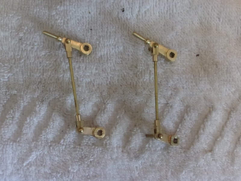
.They were assembled on the loco to ensure they had ninety
degrees operational movement and the slots in the forks filed out a little
more where needed. Next I made the glass protector covers which were made
from 26 swg brass sheet. To start, I bent them around a 12mm former. |
 |
 |
.This made it easy to set them over a piece of 12mm MDF
to drill the fixing holes and mill out the 3/16" wide viewing slot. Then
they were tidied up with files and sanding drums in the dremel. I also cut
a couple of pieces of thin polycarbonate sheet to act as windows behind
the viewing slots. |
 |
 |
Now it was time to do the final machining on the bodies,
the most important job being the drilling through of the valve spindles.
First, the valves were set in the open position and each of the retaining
nuts pulled up tight. Then the assemblies were completely dismantled, except
for the spindles, and each valve body loaded to the machine vice. Because
the spindles are tapered, there was a chance that a drill could deflect
sideways slightly so I used an end mill to create a flat area prior to drilling.
The end mill was also used to align the valve upright. The reason for using
a vice in a vice was to allow me to move over to the drilling machine and
drill the through-hole without disturbing the mill. Then the valves were
dismantled and the drilled holes cleaned up. It is important that the spindles
are not turned before this as there is a risk of scoring the inside of the
valve body. The spindles should be drawn straight out and the edges of the
holes deburred. I used a slip stone for this as there is less risk of damaging
the polished surface. |
 |
So here are the parts needed to make up a single three-cock
gauge and blowdown valve, thirty eight on view but missing the "O" rings
to fit around the glass. And here are the final assemblies mounted on the
boiler. Obviously, they have to come off again to fit the false backhead
and I will also replace the four 10BA screws holding the covers in place
with brass screws as these penetrate through to the water space. The glasses
will also need marking somehow but that's for later. It's been quite a juggling
act to get everything working in concert and they are quite fiddly to make
but I'm pleased with the end result. I can see why the commercial one are
so pricey. |
 |
| Three-cock gauges cont. |
|
|
 |
I've had some tiny weeps from the 3-cock gauges where
the tapered valve stems pass through the bodies, mostly because the tapers
are not exactly equal. This probably happened because the pressure from
the tapered "D" bit reamer distorted the flimsy bodies and there is also
a tendency for the reamer to deflect slightly. There is a great deal of
force applied when reaming a taper, far greater than for a parallel hole.
With this in mind, I completely redesigned my 3-cock gauges and made some
new ones with not a single tapered spindle in sight. First the four bodies
were remade, this time using sections from 13mm bronze plate but this time
the crosshole for the valve stem was reamed 9/32". The size was determined
by what "O" rings I had available and a quick look in the cheap-and-cheerful
selection box revealed some 9/32" x 5/32" rings. Because I need flat shoulders
for the valve spindle to bear against, I have not bothered with any shaping
at this stage. |
 |
 |
The spindles were made from 3/8" dia Colphos and the first
operation was to turn the stem to a full 9/32" diameter by 0.380" long and
with an 8BA thread on the outer end. Then I machined a pair of grooves with
a 1/16" grooving tool, touching on and plunging in fifty eight thou (0.116"
off the diameter) to give four to five thou per side of squeeze on the "O"
ring. Finally, the 9/32" diameter was polished down till it just fit in
the reamed hole and the "O" rings fitted. After parting off with a bit extra
for the handles, the opposite end was machined to include a spacing boss,
the O/D for the 3mm square drive and another 8BA thread to keep the handle
in place. Then it was over to the mill to cut the square. |
 |
 |
The rest of the machining was as previous apart from four
slim washers to fit on the outboard ends. The drain cocks at the bottom
were also made with this form of valve spindle but using 3mm x 1mm "O" rings
on a 5mm diameter valve stem. The tiny "O" rings were a pain to assemble
so a small tool was made to assist, a taper at one end and roll the ring
on, a bit like a spring compressor in reverse. However, the drain cocks
wept slightly under pressure and something even better was needed so I converted
them to miniature versions of globe valves by turning up a bung for the
cross-hole and soldering it into place. I started with some 1/4" diameter
Colphos, turning the O/D to 5mm dia for a length of 3/8", pilot-drilling
2.3mm dia to the same depth, then drilling 3.3mm dia to a depth of 1/4""
and tapping M4 for 3/16" |
 |
 |
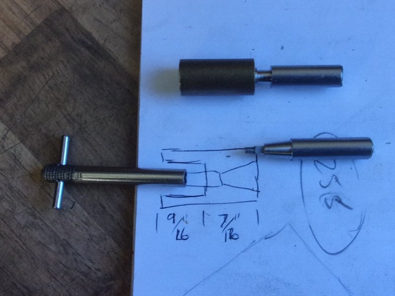
After soldering into position, the drain cock was screwed
into a mandrel and the angled hole made, starting with a 2mm slot drill
and finishing with a 1.6mm drill. The angle of the collet block was set
by eye, offering the drill to the front of the workpiece. There was not
much room for error here. This simple sketch shows what I wanted to achieve.
A 1/8" diameter silicon nitride ball was used to seal the port. The lower
hole was drilled through freehand on the pillar drill to complete the drain
path. |
 |
| And because I kept the plate that was used
to set the bushes in the backhead, I was able to fix up a test rig to check
each set for leaks without having to keep screwing them into the boiler
and risk damaging the threads in the bushes. As can be seen, the first set
is currently sitting at about 130 psi with no weeps from the drain but a
quarter-turn of the screw and away it goes. I shall now modify an M4 stainless
steel screw and fit the original brass handles. Although the parallel-stem
valves leak very slightly from input to output under high pressure, they
don't leak to the outside. This doesn't matter too much for the shut-off
cocks because they will only ever be used in a broken-glass scenario and
they will work well enough to protect the driver from a faceful of steam.
The drain is different and has to be able to hold full pressure at all times. |
 |
| 8. Next Item... |
|
|
| |
|
|