| Drawing 7 - Brake and Sanding Gear
|
| 1. Brake Blocks |
|
|
 |
I have covered the tender brake blocks in much greater
detail on drawing 22 so this is just a shorter description of the main brake
blocks. As I described previously, I first cut the strip of brake blocks
into the indivdual components followed by drilling and tapping 2BA at the
position where the pivot pin goes, this being the nearest thread size under
3/16". Then they were bolted onto the carrier plate and one side faced before
reversing and facing the opposite side. To produce the wheel profile, I
bolted some extensions onto the soft jaws and mounted the blocks as before,
using 2BA cap screws tightened up very firmly. |
 |
 |
I had previously made a wooden former the same diameter
as the main wheels and this acted as a gauge, saving me from having to remove
a wheel or axle from the build. I also approached the job of milling the
slots differently as I now had my new mill. This time a slitting saw was
used, loading the blocks in pairs in the mill vice and plunging directly
to depth gently by hand. To finish, the 2BA tapped holes were drilled and
reamed 3/16" to accept the pivot pins |
 |
| 2. Pull Rods |
|
|
 |
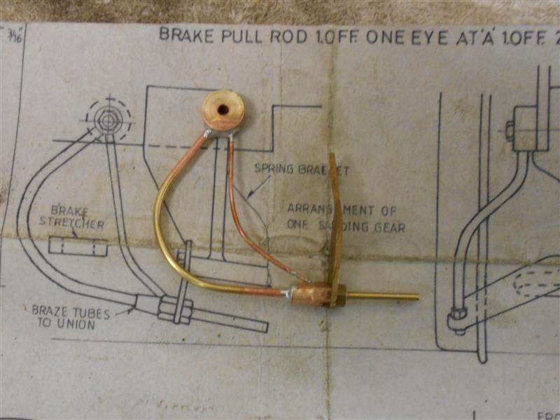
The two pull rods, along with most of the other brake
components, were made twenty years ago and no photos exist of the making
of these parts although I remember that the eyes and forks were brazed to
the rods taking care to get the alignment correct. However, I have since
found that they do not pull up evenly on all wheels and have now cut them
in two, removed 1/4" of metal and made a turnbuckle for each one using
M4 left-hand and right-hand threads respectively. The turnbuckle is from
5/16" hex mild steel at 1" long. A locknut on the right-hand end
allows fixing after adjustment. There is another picture in the "overview"
section of the complete linkage. |
 |
| 3. Sanding Gear |
|
|
 |
The sanding gear is non-functional and made from various
bits and pieces. The sand pipe is from 3/32" dia brass tube, the dummy steam
line from copper wire taken from some 1.5mm twin and earth carth cable,
the combining nozzle and nut from 1/4" hex brass and the bracket from 16
swg brass sheet offcuts. The machining of these parts is mostly straightforward
and needs little explanation. However, the drawing does show a forty-eight
thou hole at 30 degrees in the combining nozzle to fit the steam pipe to
and for this I made a simple fixture to screw the nozzle into. A 1/4" x
40 hole was tapped in a piece of hexagon brass and the hexagon rotated round
and held in a vice. This allowed the nozzle to be screwed in, a tiny flat
filed where the hole was to be and then centre-drilled and drilled 1.5mm. |
 |
 |
The 3/32" dia pipes were bent freehand using a bending
spring and the various parts were soldered together with silver-bearing
soft solder. There is also a photo on the "overview" page that
shows one set fitted to the loco. |
 |
| 4. Next Item... |
|
|
| |
|
|