| Drawing 23 - Tender Body
|
| 1. Side Sheets - bending |
|
|
 |
The tender tank is constructed almost entirely from 16swg
brass sheet and I had the main pieces guillotined from a 4ft x 3ft sheet
by a local fabricators. The two tank sides need to have bends put in them
and this would normally be done on a large folding machine or pressed to
shape in a hydraulic press. I have neither and didn't want to have to make
a large piece of equipment just to form four bends so decided to make a
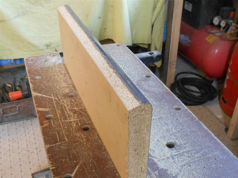
wooden former and bend them around that. The material chosen was a short
length of kitchen worktop with a half-inch radius to the front top edge.
Since this is specific to the one item, I cut the worktop a 1/4" longer
and 1" wider than the tank sides. |
 |
 |
Then, using an offcut of the same material, I clamped
it up and put a bend in to find out just where to set the tank side on the
former and to see how close to a right-angle I could get. I reckoned that
I needed to set the panel 7/8" from the back edge and about another ten
degrees undercut to the front edge. To achieve this I planed an angle on
the edge. Then I put my offcut back on the former and clouted it a bit more
with my nice new rubber mallet. I was happy with this so now I loaded one
of the tank sides to the former with a decent-sized piece of support material
clamped on the top, put the whole lot in the workmate and gently tapped
the edge over, working back and forth along the panel to keep the bend reasonably
even throughout. |
 |
 |
Eventually, I reached the point where it wouldn't take
any further set (springing off the former) and just kept gently tapping
until I had a decent straight line at the bottom. This was then repeated
with the other tank side.
The upper bend in the panels
is at twenty five degrees from the horizontal and to form this I first had
to reduce the size of the former and chose to saw it down to five inches
wide. |
 |
 |
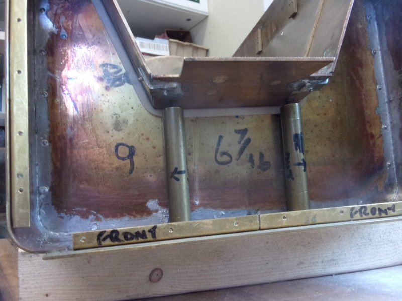
Then the offcut from earlier was clamped to the former
with a half-inch spacer at the back and the metal tapped down until the
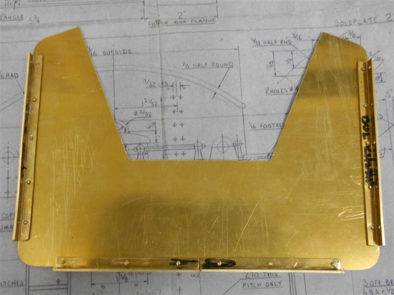
twenty-five degrees was achieved. This was then offered up to the drawing
to check the angle and to see what distance to set the rear spacing at.
As you can see, it's about 7/16" short so the spacing needs to be 15/16".
I put a couple of wood screws in the back of the former and set them to
this depth, in such a position that they would not foul the bend on the
material. I also set another piece of timber, which I planed to twenty five
degrees, at the back of the fomer to act as a stop. |
 |
 |
This time, I also clamped a support bar to the part of
the tank side that I would be hammering over because this should help keep
the sides straight. However, I found that this was too restrictive and I
couldn't get the material to bend so I went back to the freehand method
and slowly worked the material down till it hit the stop. And I now have
two tank side sheets ready for the next operations which are to remove the
surplus material from the top bent section and then drill all the holes
- a heck of a lot of them. |
 |
| 2. Side Sheets - machining |
|
|
 |
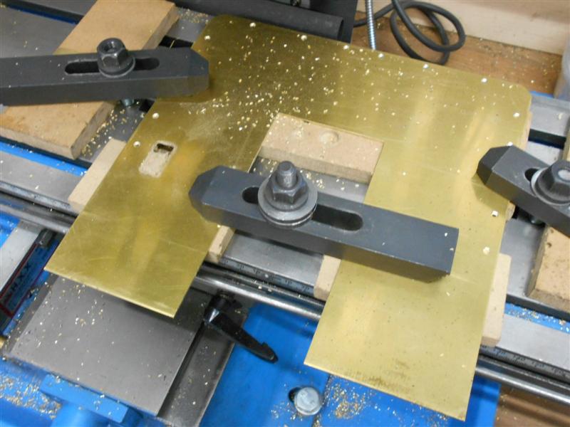
Once the bending work was finished, the tank sides were
clamped to the mill table and had the lower section that connects to the
sole plate reduced to the correct size. This was done with a small end mill
but it chattered quite a bit until I balanced the cut at about thirty degrees.
The next job was to drill all the 3/64" rivet holes, one hundred and thirty
per side, and this was done on the milling machine using co-ordinate drilling
with the DRO. It wasn't possible to do them all in a single setup so each
tank side was placed as far to one end of the table as possible and holes
drilled until past the half-way mark. The sides were then moved to the other
end of the table, a previous hole picked up for reference, and the rest
of them drilled. |
 |
 |
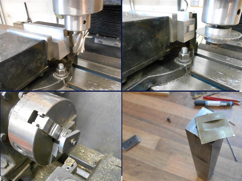
This was followed by mounting against an angle plate and
the 1/16" dia holes drilled in the lower section for riveting to the sole
plate. Another job that required attention was to reduce the length of the
upper tank section to the correct size for abutting the coal bunker. This
was done by setting a slitting saw at the correct height above the mill
table and the tank sides clamped down. As required, extra clamps were added
to hold the centre section firmly to the table and dampen any vibration
set up by the cutter. |
 |
 |
Clamps were also added to the section that
had been cut just in case the cutter grabbed and caused any probems. This
was simply a case of taking my time and feeling my way along the cut. After
the half-way stage, the work was moved to the other end of the table and
continuing to the end. I stopped 1/8" short of the end and finished separating
the parts with a hacksaw. There are more holes required for fixing the support
angles to but I will drill these once the angle pieces are made. These will
be joined with 8BA countersunk brass screws and sealed with soft solder. |
| 3. Rear Panel |
|
|
 |
As with the tank sides, I had the rear panel
guillotined from the 1/16" brass sheet and was pleased to find that the
sizes of all the cuts were within ten thou of my requested dimensions. The
drawing doesn't specify whether the end panel should butt up on the outside
or fit inside the tank sides. I have chosen to have the end panels outside
and are sized accordingly. The rear panel was clamped onto a piece of MDF,
trued up and all the holes drilled using co-ordinate drilling on the mill
using the DRO. The drawing also calls for the panels to be riveted together
with brass angles internally but I have chosen to use 8BA countersunk screws
to fix the panels. These will be filled and rubbed down after assembly is
complete. This is how the Modelworks tender appears to have been constructed
and it means I can dismantle the tender at different times as needed. Riveting
everything early on means any modifications become much more difficult to
execute. Once assembled, the form of the tank sides was scribed onto the
rear panel, the panel taken off and the waste removed with hacksaw and files. |
 |
| 4. Centre Bracing Panel |
|
|
 |
In a departure from the drawing, I made a centre supporting
panel to add a bit of strength to the tank sides and to create somewhere
to add two more brass angle supports. It fits just behind the coal bunker
and has a piece of brass angle to support the rear of the bunker and has
another piece on the other side to support the rear top plate. It was made
1/16" shorter than the internal height of the tank and the top plate sits
on it, butting up to the coal bunker. As before, all holes were drilled
using co-ordinate drilling, and the centre sections were removed by drill
3/8" dia holes at the corners and milling out with a 1/8" end mill. Brass
angles were made to suit which were riveted to the centre panel with 1/16"
brass rivets. The panel is fixed to the tank sides and sole plate using
8BA brass countersunk screws. This panel is similar to the one that Modelworks
used in their variation of this tender. Thanks are due to John Johnston
for the photos of his 5" gauge Britannia that showed me how these parts
were made and utilised. |
 |
| 5. Front Bulkhead |
|
|
 |
The front bulkhead forms the forward extremity of the
water tank leaving a short space between it and the front panel for the
lockers in the centre and the water scoop and brake operating mechanisms
on either side. This was made to be as close a fit as possible between the
tank sides and sole plate to facilitate soldering and the fixing angles
are riveted to the panel. As with the other panels, I have chosen to fix
the panel to the tank sides and sole plate using 8BA screws. The locker
section is removable to give the driver easier access to the footplate when
firing and driving but is replaced when on static display. |
 |
| 6. Bunker Floor |
|
|
 |
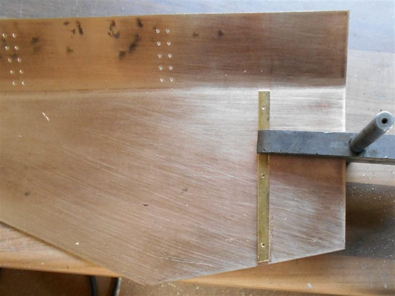
I have made the bunker floor and the rear panel from a
single piece of material, this time it's an old brass kick-panel salvaged
from a discarded office door. Apart from the rear section, which is dimensioned
as per drawing, the rest is scaled as no dimensions are given, it's a case
of bend-to-suit. To set the radius of the uppermost part, an indent was
made on the centre-line at the correct point and a compass with scriber
used to mark out. The waste was then removed with a hacksaw (with the blade
mounted sideways) and the edges filed to clean up. The dark colouration
in the photo comes from the varnish coating and this was removed with emery
on a sanding block. |
 |
 |
Before bending, I set the panel up on the mill and drilled
the four rows of holes in the rear section. This was then followed by clamping
the top section between two pieces of large flat steel and bending the floor
section to approximately twenty two degrees and repeating with the rising
section to about eighty degrees. These were then eased until a nice fit
was obtained at the front bulkhead and the 2.3/16" reference dimension for
the lowest point was attained. There is more to do on this section but I
will wait until I have made the bunker sides and the lift-out section before
finishing this. |
 |
| 7. Bunker Sides |
|
|
 |
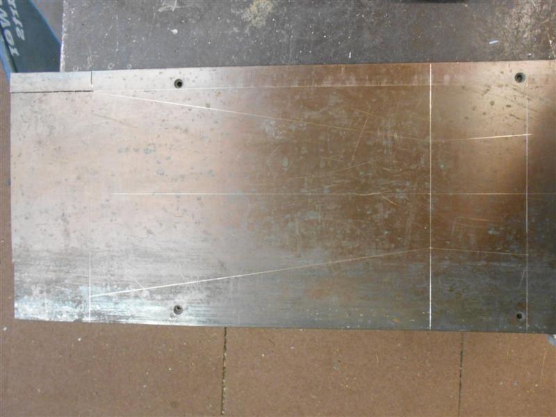
The bunker sides were marked out on another salvaged door
kick-panel using a cardboard template that I made to ensure the developed
form came out correctly. I managed to get these cut with the minimum of
waste by using a common centreline between them. The panels include both
the angled sections as well as the vertical sides and a bend was marked
out by placing them into the framework, resting on the bunker floor, and
marking each end point from the tank sides, then scribing a line between
the points. These were then bent to approximately twenty degrees and offered
up but a fair few sessions were needed before I had a good fit to the bunker
floor and vertical sides that were actually vertical. Some adjustment was
also needed on the ends because the bend changed the angle of the rear upright
by a few degrees so I filed this back to square. |
 |
Once happy with the fit of this, I then removed
the surplus that I had left on the top of the vertical sections to the specified
1.1/2" height by clamping on the mill table, clocking out the bending line
and milling the waste with the side flutes of an end mill. |
 |
| 8. Removable Front Section |
|
|
 |
The front panel needs to be made in conjunction
with the removable section but I will cover this as a single entity following
this part. I have no intention of making any of the locker doors to be opening,
nor am I bothering with the actuating gear for the scoop and the tender
brakes. The handles will be fixed dummies, and the tool tunnel will be modelled
at the front but only for the depth of the removable section. When in use,
a drop-in panel will replace the lift-out section to retain the coal but
when on display, a dummy tray depicting a full load of coal will be used.
Therefore, I also feel that to model the full length of the tool tunnel
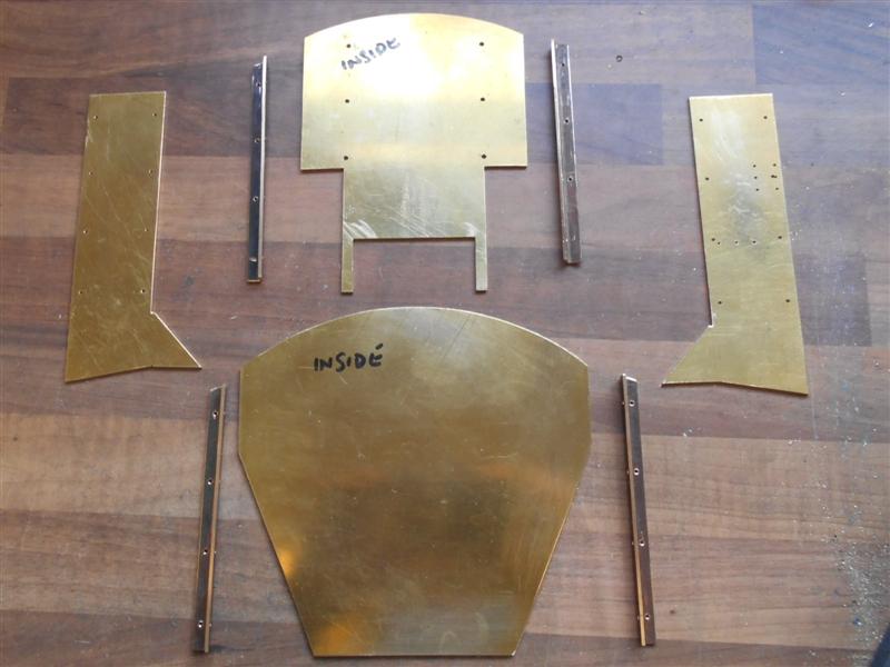
is a waste of time and material. Here are the various parts that make up
the removable section, all made from 16swg brass and some more home-made
angle. The extra holes in the right-hand side panel have no purpose, I've
just used up a previously scrapped item. . |
 |
All the parts were bolted together and, as can be seen,
the angle extends down past the wider section and acts as a locating face
to bear against the front panel. The side panels and the tops of the angles
are set down by 1/16" to allow the roof to rest on them. The assembly was
then offered up to the tender for fitting and I could see that the sides
of the coal opening were too angular, projecting past the coal plate, and
needed taking back a little. Also, it didn't sit too square in the opening
and was pulling backwards slightly at the top right-hand corner. |
 |
 |
I decided to make the roof section next to see if that
would pull the whole thing square and a section of brass was cut a lttle
longer than needed and the same width as the side panels so that it would
slot in to the assembly. I don't have any bending rolls, and I was too impatient
to wait until my next visit to the club, so opted to form the radius using
the nearest available piece of kit. Using the topslide to trap the lower
edge, I formed the radius around the chuck by hand pressure alone and then
eased it back freehand to fit nicely in the lift-out section. |
 |
 |
The ends were then trimmed to length and the
assembly offered back into the frame but it still didn't fit as nicely as
I would have liked. Laying it flat on the surface table, there was a noticeable
rock along the 2pm - 8pm axis so I decided to dismantle everything and skim
the sides of the angles again, remembering that they were now riveted to
the side panels. I set up the small angle plates on the mill and skimmed
the edges of the inner panels to about a ninety percent cleanup, reducing
both parts by the same amount. Approximately fifteen thou in total was removed.
|
| Of course, this meant that the roof section
also had to be reduced by fifteen thou and this prompted an interesting
but unusual setup to enable the milling of the edge. Winding both handles
of the mill at the same time to keep the cutter working all the time takes
a little getting used to, and I found that it chattered slightly in conventional-milling
mode but performed much better when I moved the cutter over and worked in
climb-milling mode. Being a heavy table and making a fairly light cut, this
presented no problem for the mill. Upon re-assembly, the whole thing was
offered back into the frame and is now a much better fit so I will leave
any further tweaking until after I have soldered the various parts together.
|
 |
| 10. Front Panel |
|
|
 |
The front panel has been made in a similar fashion to
the other panels and has been seen in the previous pictures. After offering
up and scribing round the tank sides to get an outline, I next cut out the
hole for the water-level gauge, being careful to work right-side up because
of the countersunk screw holes. I then cut out the widened section of the
front plate. I have opted to remove the section just above the water scoop
and brake gear panels and I set the width based on the dimensions for the
edge of the tool tunnel. However, photos of Britannia show that the drawing
is wrong and the tool tunnel is much wider than drawn. I really should toss
these drawings in the rubbish, where they belong! |
 |
 |
The insert for the removable section of the front panel
was clamped to the face and marked out prior to cutting. On the front plate
itself, I have now produced the cutaways on the lower section that reveals
the brake linkages and scoop operating shafts respectively. I milled a 1/8"
slot along the top first, then hacksawed the rest out.I find this much more
satisfactory than chain-drilling, bending out and filing to size. |
 |
 |
I also clamped a couple of the previously-made window
frames (next page) to the panel, 1/8" in from the edge, and spotted through
to create the mounting holes. Rivets were then dropped through and the internal
shape scribed onto the front plate. I was lucky to find that a 16mm hole
saw passed through the window opening with a room to spare so the centres
of the windows were marked on the panel and then drilled through, followed
by filing out to size. |
 |
 |
Finally, I have made the tool tunnel cutaway in both the
front panel and the lift-out section, marking out by scaling off the drawing
for part of it and freehand with reference to a photo. Here, I have offered
it up to the tender to see how it matches with the bunker sides. Quite a
few of the tenders that I have seen have made the tool tunnel too narrow.
It should extend to be in line with the edge of the brake panel. A little
more filing was needed when that picture was taken. To the right is a photo
of the panel with the locker doors cut from brass shimstock and laid on
the panel. |
 |
 |
The last work to have been done on the tender front panel
was cutting out the triangular cutouts below the scoop and handbrake handles.
I have now "ironed on" the two brass shimstock panels just above these and
have been set with some 3/64" rivets to mimic the retaining screws seen
in the photo. The holes for the brake and scoop handles were also drilled.
The bosses were made from 3/8" dia brass bar turned to about 1/4" dia to
better represent the full-size item and with a 6BA thread on the other end
for fixing to the front plate. The handles are from 2.5mm brass rod. |
 |
 |
These handles are dummies and will never be turned so
the shoulder represents the boss on the bulkhead. The only thing that was
less than straightforward was drilling the handle holes at twenty degrees
and this was achieved with a simple drill jig to steady the drill. The box
section below the coal plate has been made from a piece of 16 swg brass
sheet soldered to a pair of 3/8" wide x 1/8" thick brass strips and held
on the front panel with 6BA screws from behind. The 6BA holes were drilled
and tapped before soldering together and the mounting holes in the front
plate drilled to suit. |
 |
 |
I decided to have a try at forming the water gauge using
a punch and die arrangement. The drawing shows the radius of the gauge face
as 1" and set into the front panel with a raised rim. A photo, however,
shows the gauge set behind the front panel so this is what I have tried
to create. I started by cleaning up the end of a piece of 1.1/4" square
bar on the mill and then cutting a recess into the end using a slitting
saw, making multiple entries at 1mm height intervals. To make the punch,
I turned a piece of flat bar to 1/16" less than the diameter of the slitting
saw. Then I cut a piece of 26 swg brass sheet about an inch square, put
it on top of the die and gave the punch a whack. As can be seen, the first
effort was less than successful, practically chopping the middle out. I
then rounded off the edges of the punch and cut a new piece of material
from 24 swg instead. |
 |
This was more successful and a little tapping
of edges soon had it looking reasonable. I cut a slot in the front using
a junior hacksaw and made a tiny indicator from some six thou shimstock,
folding it round, soldering together and cutting the shape with a tiny chisel.
All these parts were then fixed to the front panel. The coal dust deflection
plate has also been made and fitted but is as per drawing rather than prototype. |
 |
| 11. Bunker Assembly |
|
|
 |
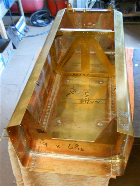
It's getting near the time to solder the bunker panels
together so I have been adding any extra features while I can still lay
the panels flat. The first of these are some guide rails behind the removable
section to help hold this in place. To help with keeping the bunker rigid
and in shape while soldering, I have also made a range of brackets to enable
me to screw the panels together. The brackets were all made from offcuts
of the 16swg, with one hole drilled and tapped 8BA and then the bracket
bent to the correct angle. The floor panel was drilled for 8BA clearance
and countersunk to allow the screws to be recessed slightly. The bunker
was reassembled inside the tank and the mid position of each bracket marked
onto the side panels. |
 |
 |
The panels were then removed, an 8BA clearance hole drilled
1/4" in from the edge and the panel replaced in the tank. The other leg
of each bracket was spotted through the respective panel holes and then
removed, one at a time, and drilled and tapped 8BA. Because I will be making
a dummy coal tray for the top, I also made internal corner brackets for
the rear of the bunker. These serve a dual purpose - holding the bunker
sides in the correct position, and acting as resting points for the underside
of the coal tray. They have been made with greater accuracy than the other
brackets and are precisely 1/2" below the top. Other resting points have
been added at the opposite corners and half-way along, making use of the
rows of rivets visible on the outside. All the rivets in the end and sides
have been fixed, as well. |
 |
| 12. Water Gauge Hatch |
|
|
 |
The water gauge access panel is not often modelled on
BR standard tenders, although I have found photos of a few examples, and
I have decided to incorporate this feature on my own. There is no mention
of this panel on my drawings but reference to a photo of the real Britannia
and her tender gave me enough to get started. This is only on the left-hand
side of the tender. One of the problems with making this as a cutaway and
fixing a panel behind the tank skin is the position of the fixings. Looking
at the photo, it shows the screws, bolts, whatever they are, on the inner
section of the panel, which requires something further below to fix to.
The other problem is one of scale. My tank sides are from 16swg material
which would represent the tender being originally constructed from 1/2"
plate!. I decided to mill away a recess and incorporate dummy rivets which
should look reasonably authentic after a coat or two of paint. I started
by mounting the side panel on one of my general-purpose milling fixtures
and supported the outer end with packing to dampen any vibration. |
 |
 |
Using a 1/8" slot drill, I milled away the area to a depth
of 15 thou with multiple back-and-forth passes and a final series of cuts
around the periphery. The section was then given a quick rub-over with a
fibreglass pencil to smooth out the tram lines. This was followed by drilling
the fixing holes, which I worked out by scaling from the photo. It's not
particulary accurate but close enough for this purpose. To finish, twenty
3/64" copper rivets have been soldered in the holes, and the two eyes were
appropriated from the dolls house accessories, part of our hook-and-eye
door closers, also soldered in from below. |
 |
| 13. Soldering the tank |
|
|
 |
There were only the two long seams to join
and one side was a close fit requiring no extra work to solder together.
The other side, however, had a gap of about 20 thou for a fair distance.
I didn't want to start pulling things about at this stage as I now have
the bunker sitting nicely in the tank. To fill the gap, I flattened some
copper wire and tucked this in along the section before fluxing up and soldering.
Once it had all cooled, I gave it a good scrub in the sink with hot, soapy
water and then inspected it for leaks. There was one area in one of the
corners where the gap was just too large for the solder to hold so a snippet
of copper wire was soldered in to seal. It's not the prettiest soldering
job around, but I filled the bunker with water, levelled it off and sat
the assembly on some kitchen roll. Eight hours later, the kitchen roll was
still dry so the job was a success. Next, I soldered all the rivets on the
rear panel, followed by the brass angles fixed to the sides and bottom to
ensure no weepage around the fixing screws. I also soldered all the rivets
on the tank sides while I had unfettered access. The hold-down screws and
overflow pipe fitting were also soldered to the sole plate. |
| The position of the two bulkheads were checked
and where the rivets fouled, these were dressed back flush and a touch more
solder applied. The tank sides were now fixed to the sole plate with 1/16"
brass rivets.One thing I noticed on completion was a few places where some
daylight was visible through the joint between rivets, possibly because
the underside edges of the tank sides were not perfectly flat or because
I was too heavy-handed when fixing the rivets. Anyway, something to watch
out for. A small amount of light hammering with a drift helped close the
gaps and the solder will complete the job but there is a limit to how large
a gap solder will fill, prefering to flow out rather than solidify in situ.
The next stage was to fix the rear panel in place with the side fixing screws
and solder the vertical joins to the tank sides. There was no mechanical
fixing of the rear panel to the sole plate at this time so I fixed small
clamps on each of the hold-down angles on the outside and used a length
of copper wire as a fillet along the inside bottom of the tank. Once complete,
the rear panel will have screws fixing it through the sole plate to the
underframe to provide some mechanical strength. |
 |
 |
I soldered the rivets and the bottom joins
next, working from the back panel forwards one side at a time. Again, I
checked the position of the two bulkheads and dressed back any protruding
rivets. This was followed by fixing the middle bulkhead and soldering the
side screws from the inside, then upending the tank and soldering the bottom
screwheads from the outside. The final session was to fix the front water
bulkhead in place and solder all round from the outside, although this becomes
inside once the front plate is fixed in place. This was a little more awkward
because the shaping wasn't perfect and I swapped over to an old-fashioned
stick of "Genuine Virgin Solder" that dates back to the 1950's because this
seems a little less runny than what I was using before. |
At this point, I performed a leak test and
found a couple of small weeps from the sole plate and one from the rear
bottom corner. The ones from the sole plate closed after a reheat and more
solder but the one in the bottom corner was more stubborn, requiring a couple
of sessions with new flux as well as extra solder. Once sealed, I filled
the tank with water, as far as was possible, and left it overnight on a
towel in a growbag tray. Next morning, towel and tray were both dry and
this just leaves soldering the bunker into place but I shall hold this over
for a while and complete the front panel first. The solder work is very
scruffy-looking but it will never be on view, so unimportant. |
 |
| 14. Water Feeds |
|
|
 |
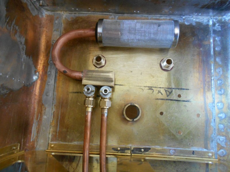
Although the filter boxes will have fine gauze
filters in them, I have made an additional filter and control block for
feeding water to the injectors and axle pump. I didn't even sketch this,
just made a block withe a central hole and a pair of tapped cross-holes
to take some valves. A bit of copper tube was bent to put a filter onto
and a couple of simple brass valves made to restrict the flow of water.
I'm not worried about them leaking, they are under water with equal pressure
both sides. |
 |
A pair of 1/4" pipes carry the water to the filter boxes
via a brass right-angle block which is soldered to the tank by the filter
box packers. This assembly just rests in the bottom of the tank and relies
on the pipes to keep things in place. The two connectors seen here are for
the hand-pump outfeed and the axle pump return. The four fixing holes are
for the hand pump which sits on a riser block and has a couple of rubber
gaskets between them and the tank. |
 |
| 15. Fitting the Bunker |
|
 |
Most people just solder the coal tray into place and
that's it! The tank is sealed for life. I've chosen to make mine removeable
just in case I want to get in there at some point in the future and I've
now made the final parts to achieve this. The tray rests on the forward
bulkhead which has a rubber seal all round the edge and is screwed on to
a pair of pillars to pull down onto the rubber. Screws at the top of the
tank sides hold the back in position and will be painted but left unfilled.
The pillars are 1/2" dia brass with the top milled at 10 deg and tapped
6BA so that the screws line up with the slope of the tray at this point.
I've had the tank 3/4 full of water overnight on a towel and it's still
dry. There is no pressure involved here, just the head of water which is
minimal. |
 |
| 16. Next Item |
|
|
| |
|
|