| Drawing 4 - Coupling Rods |
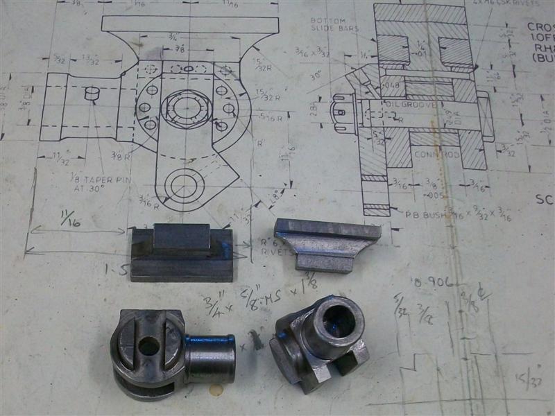
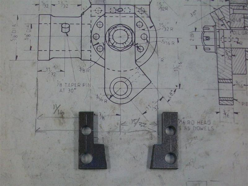
| 1. Slide Bar Brackets |
|
|
 |
I have made these using the gunmetal castings that are available since
they are a better casting than some of the other offerings for this loco.
However, I made these parts sixteen years ago and don't have any pictures
of how I made them. I was also able to use the Bridgeport with its DRO so
was able to make them much more easily than if I had to make them today.
I do have my notes to refer to and will describe how I made them as best
I can. First job was to machine the outer edges to get them square and to
finish sizes. |
 |
 |
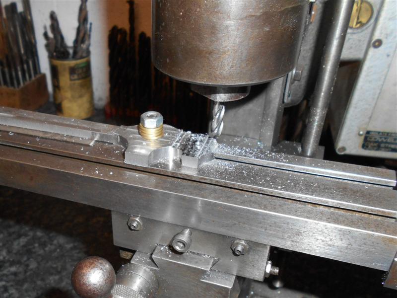
Then they were dropped into a large milling vice and the back
face cleaned up followed by some work on the underside, just to pretty them
up. Next I drilled and tapped the 8BA holes for the lubricator mounting
plates and also the holes for mounting the slide bar brackets to the mainframes.
Usually, these would be spotted through from the frames but co-ordinate
drilling with a DRO is far more reliable than marking out by hand. The job
that needed reasonable care was the machining of the angle where the top
slide bar bolts to. Although the angle is not shown, dimensions are given
to indicate the change of height over the width of the bracket. For me,
this is a job that can most easily be done with a sine bar and I calculated
the slips needed to lift the bar to the correct angle. In my case, the sine
bar centres was 6" and the width of the slide bar bracket is 2.1/4" so multiplying
the amount of rise (0.182" - 0.080" = 0.102") by 6 and dividing by 2.25
gave me 0.272" and slips to this value were wrung together and set under
one end with the whole lot set up against an angle plate. |
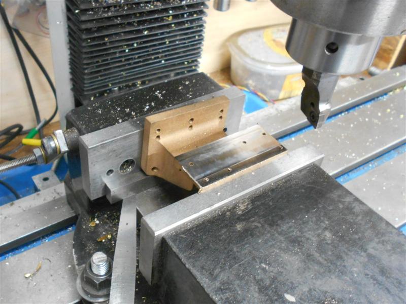
| The slide bar bracket was then clamped to the angle plate
and the surface machined. Using the same setup, I also drilled the slide
bar mounting holes using co-ordinate positioning with the DRO. Finally with
this setup, I upended the casting and cleaned up between the webs and the
end sections so that the bolt heads had a machined surface to locate against.
To complete these parts, the rib nearest the cylinders was cut back to provide
clearance for the rear valve guide and the castings given a bit of cosmetic
work with a sanding drum in the dremmel. The lubricator mounting plate is
just a couple of bits of 16swg brass cut to shape, drilled, and soldered
together prior to bolting to the top of the slide bar bracket. I have deliberately
drilled the holes in the frames four thou larger than usual to allow a bit
of adjustment when the time comes to set everything up. I have also reduced
the width of the slide bar brackets by 1/16" to facilitate the mounting
of the footplate brackets that fix to the frames right next door. The drawing
dimensions are incorrect and the footplate brackets cannot possibly fit
as drawn. |
 |
 |
Update:
I had left the slidebar brackets unfinished at the first machining to ensure
accurate alignment of the crosshead and piston rod. This became evident
when I mounted the cylinders and tried to align the crossheads. They are
in line vertically but need more machining on the slidebar mounting face.
It was simple to measure the difference in height between the two rods so
the slidebar bracket was duly dismantled and taken to the milling machine.
The angle is already correct so it was only neccessary to clock the face
true and remove the extra material. |
 |
 |
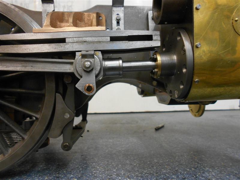
After removing the surplus, seventy-two thou
on the first one, it was remounted but still just a tiny bit sticky. The
frame-mounting holes were opened up an extra 0.1mm - four thou - and this
allowed enough adjustment to get a nice smooth action through the piston
rod. With six 4BA screws holding the bracket in place, it isn't going to
move once clamped up tight. The procedure was then repeated for the other
side. |
| 2. Slide Bars |
|
|
| Although the drawing specifies mild steel,
I have made the slide bars from ground flat stock using 3/4" x 3/16" for
the upper bar and 1/4" x 1/4" for the lower two bars. The reason for choosing
this material was because it has exceptionally good straightness and I want
the crosshead to travel along the guides without any high spots causing
binding. I also milled down a couple of offcuts of the 1/4" square to make
the packing pieces for either end, making sure I had them both of equal
thickness for the same reason. The relief sections of the bars were milled
out first followed by the angled sections at each end of the bars. Finally
the holes were marked out, taking special care to get them accurate because
I want a good fit to the flimsy 8BA bolts that will hold the assembly together,
and then drilled and tapped accordingly. They need a bit of a polish and
the edges stoning to finish |
 |
| 3. Crossheads |
|
|
 |
I have made the crossheads from 1" square EN3B bar although there is a casting available. The drawing appears
a little confusing, or maybe it's just me being dense, but working with photos I took of Oliver Cromwell many years ago at
Bressingham I think I have them looking a fairly reasonable compromise. The first job was to linish the back face which became
the datum face for marking out. Then the blocks were loaded to the 4-jaw independant chuck and faced to overall length on the
first op and to 29/32" thickness on the second op.
|
 |
 |
Now they were marked out again to provide the centre of the raised boss, centre-popped and returned to the 4-jaw.
The boss was then turned to 3/4" dia by 5/32" deep leaving the main crosshead thickness at 3/4". The next part of the job was to
machine the spigot that the piston shaft locates to and drill, bore and ream the hole to 3/8" dia. The drawing shows the raised
part of the collar as 5/32" long but the photos indicate otherwise and I have made mine approx 1/16" long. |
 |
 |
The slot needs milling out to 3/8" to take the little end of the con rod and also the upper tee-piece but because
I only have a very small milling machine, I drilled away a fair amount of material first. The slot was then formed with multiple
passes of a 6mm slot drill followed by a 8mm slot drill. After this, I tossed them to the back of the bench for a week to settle.
Being cold-drawn mild steel, they are bound to warp a little bit, probably with the sides springing inwards a bit. . |
 |
 |
A week on and
they had moved less than I expected, just a couple of thou difference between top and bottom. So I set up the faceplate again and
finished them off with a 3/8" cutter, also making a back and forth pass a couple of thou to one side to finish about 0.378". Then
they were turned ninety degrees and the top milled out for the tee-piece and reduced in height by thirty thou to get the 15/32" from
centre about right. Next I made the tee-piece for the top half and for this I used cast iron. A couple of billets were sawn from an
old sash weight and faced to length in the lathe before being milled into rectangular blocks. Then the slots were cut on the milling
machine. |
 |
 |
I finished the 5/32" dimension to size but the drawing calls for 1/4" minus ten thou for the waist and I think this will be
too sloppy so I've made mine minus three thou. If it turns out to be too tight then it will be fairly easy to adjust the bottom slide
bars to compensate. Then the bottom part of the tee-piece was milled down to finish with a squeeze fit into the top of the crosshead
and then shortened to match. The final milling job on these was to use my small flycutter to form the 15/32" radius on them. |
 |
 |
They were now ready for joining together with rivets. After making sure that they fitted together OK I then made a
couple of 9/32" spacer bars to help accurately set the two parts in position. They were then clamped together in the vice and four
cross-holes drilled 1/16" diameter ready for rivetting together. Although they look a bit scruffy at the moment, two of the rivets
will be under the vertical arm, or droplink, and won't be seen while the other two will easily be lost under a coat of paint. The
crossheads were then assembled into the slide bar sets to check for fit and movement and all appeared to be in order at this stage. |
 |
 |
Next I had to make the droplinks and for this I hacksawed a couple of blanks out of a piece of 3/16" flat bar
stock.Then they were cleaned up in the milling machine and the two main holes marked out, drilled and reamed to size. I also made
a filing button ready for the next stage. |
 |
 |
Next, the angled face was marked out and milled away (there is some sacrificial packing behind the workpiece)
followed by marking out around the filing button, sawing away most the waste and linishing to shape. Then it was time to reduce
the thickness to 1/4", leaving the raise section for shaping up later. |
 |
 |
To shape the raised oilbox section I used two methods but forgot to take a picture of the first part of the job.
The angles of the section are 30 and 60 degrees respectively and this is a perfect job for an adjustable angle plate. Unfortunately
I don't have one but I did have some bits of hexagon mild steel in the scrap box and a simple fixture was fashioned from a piece of
this - actually just an M6 tapped hole through the bar. This was then held in the milling vice and the arm bolted to it, lining up
purely by eye. There is very little to come off and easily achieved with light cuts. The underside was done differently using an
angle plate, with a bar set at 30 degrees. |
 |
 |
Finally, the first of the two oil holes were drilled just
held in the vice and drilled freehand. The second was loaded onto the hex
bar exactly as it was for milling and again drilled freehand. The only pieces
left to make were the gudgeon pins which were made in a single operation
on the lathe from some 1/2" mild steel and the phosphor-bronze bush at the
bottom of the droplink which was made as a press fit, pushed in, reamed
to size and finally the oil hole drilled through. |
 |
| Then the whole lot was bolted together and set in their respective
guide bar assemblies. Once assembled, one side was a bit sloppy with some
vertical play so I reduced the spacer pieces on that side by a couple of
thou and achieved a much better fit. |
 |
| 4. Front Coupling Rods |
|
|
 |
I have made all of the coupling rods from general purpose black mild steel,
probably EN3 grade, because I think there is less chance of the rods distorting
after machining. The material I am using came from a forge that manufactures
gates and railings. The first thing I had to do was get them finished to
length and one edge cleaned up so that I could mark the outline of the front
rods onto the surface. After this, I marked out the centre-line of the bearing
bores and the distance in of the first bearing, and drilled a 1/8" hole.
Then, using my beam compass, I accurately set the distance between the leading
and centre axles and then transferred the second hole to the front rods. |
 |
 |
Next, I finished marking the rods out and drilled the third bearing position
and I shall spot through this hole when I make the rear rods. Back to the
lathe and plenty of roughing out with a 12mm centre-cutting end mill (because
I have loads of them) and then over to the vice and an hour with a carbide
burr and sanding drum in my dremel. I have used 8mm thick material so they
need thinning down to 1/4" and the coupling rod reduced again to 3/16".
This was done with four setups each side due to the travel of my mill table. |
 |
 |
To get the transition from the the 1/4" thickness to the 3/16" I bolted
the rod to a small faceplate and used a 10mm end mill to form the radius.
This is the maximum size endmill that I can hold in the Cowells mill. I
smoothed the transition further using a sanding drum in my dremel. The holes
for the phosphor bronze bearings were opened up to size using a stepped
drill. I don't have a 5/8" reamer but it doesn't matter as I shall make
the bearing to suit. As long as you have control over one or other dimension
that is all that is needed to get a good fit. |
 |
 |
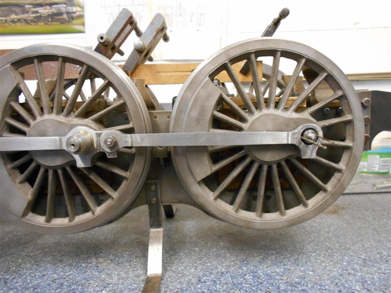
Prior to making the bushes, I offered the front rods up to the loco with
the crank pins set at exactly the nine o'clock position to see if they were
going to fit but it soon became obvious that my hole positions were not
accurate enough. I decided to make the bushes with a deliberate offset so
that I had a bit of adjustment available. First, I made up a couple of top-hat
blanks, without the hole, to the correct sizes in the 3-jaw chuck. Then
I put the 4-jaw independant chuck on the lathe and loaded the blanks one
at a time, clocking the O/D to get a total indicated runout (TIR) of about
twenty five thou. |
 |
 |
Next I drilled through with a 1/2" drill, stopped the lathe and let the
pressure off the chuck as I didn't want them deforming - the wall thickness
is less than fifty thou at one position. Phosphor bronze is one of my most
hated materials to work with, drilling the hole is a pain because the stuff
heats up and expands very quickly during cutting, then cools and contracts
causing the drill to bind. A good tip is to grind the anvil of the drill
slightly off-centre which causes the drill to cut on one side and, consequently,
slightly oversize. This stops the binding, but you need to be able to regrind
the drill to its correct form for normal use. |
 |
 |
Then I just nipped them up again and bored to the 5/8" finished size
with a nice, sharp HSS boring bar. I don't have any particularly accurate
instruments for measuring small bores and nor do I have a reamer so used
a stepped plug gauge. Before trying to fit the first rod to the wheels,
I aligned the crank pins on the wheels nearest to me at bang-on the 9 o'clock
position and locked them together with a piece of flat bar clamped to the
wheels on the other side. This made sure they stayed perfectly in position.
|
 |
 |
Next, I pressed the new bearings fully home - I had made them a light
press fit - and by holding the shoulder of the bearing in the bench vice,
I was able to rotate the bearing round to different positions until the
rod slipped easily onto the crank pins. Leaving this front rod in place,
I turned the loco round ( no mean feat as it's getting pretty heavy now)
and repeated the whole procedure for the other side. Once I had the other
front rod a sliding fit on the crank pins, I removed the clamp bar and tested
the rotation of the wheels. I am pleased to say that the wheels rotate freely
with no hint of binding as the crank pins pass the E-W positions so that
proves that my crank pins are in the correct position relative to each other
(drilled with a drill jig) and that my wheel quartering is also accurate
(using keys). To finish, I just need to drill the oil holes in the top of
the rods. |
| 5. Rear Coupling Rods |
|
|
 |
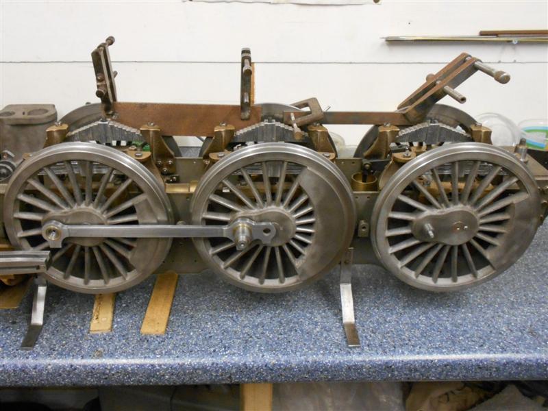
I have made the rear coupling rods in a similar fashion to the front coupling
rods as described earlier and using the same 8mm black steel that I bought
from the forge. It has actually been a nice material to work with and quite
unlike some of the GCQ (Good Commercial Quality, although we used to call
it Generally C**p Quality) that I've machined in the past. After marking
out and drilling I machined the main part of the rods on the lathe (see
previous post for pictures) followed by forming the shapes of the bosses
with carbide burrs and sanding drums in the Dremmel. |
 |
 |
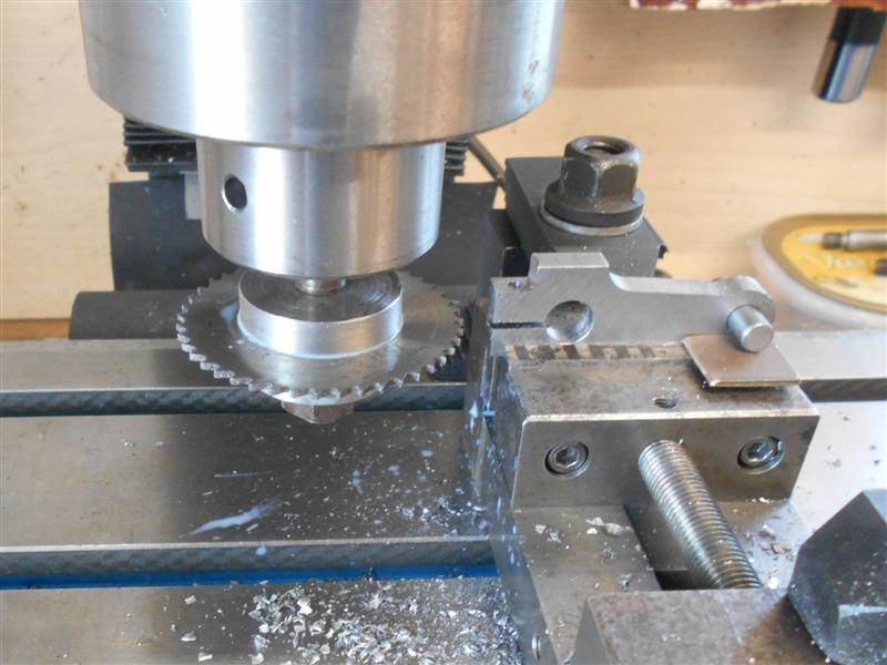
Then the arms were thinned to 3/16" on the milling machine followed by
drilling the holes and dressing at the workbench. I also had to put the
5/32" slot in at the driving end and opted to cut this using a slitting
saw mounted in the lathe chuck. |
 |
 |
Being a little wiser this time, I knew the holes wouldn't be that accurate
and have made the bushes in the independant 4-jaw chuck from the off. I
started by setting up the wheels with all the crank pins at the nine o'clock
position on one side and clamped the wheels in position, making sure that
the front rod slid easily into place. Then I removed the rod, coupled it
up to the rear rod and offered it back up to the crank pins. This time I
was able to use miniature drills as feelers to find how much offset I needed
and once I knew this figure, I added a couple of thou to give me the amount
of runout (TIR) I needed to set on the O/D of the bush. |
 |
 |
The phosphor bronze bush was then made the same way as last time, pressed
into the rear rod and adjusted until all was a nice fit. Then the loco was
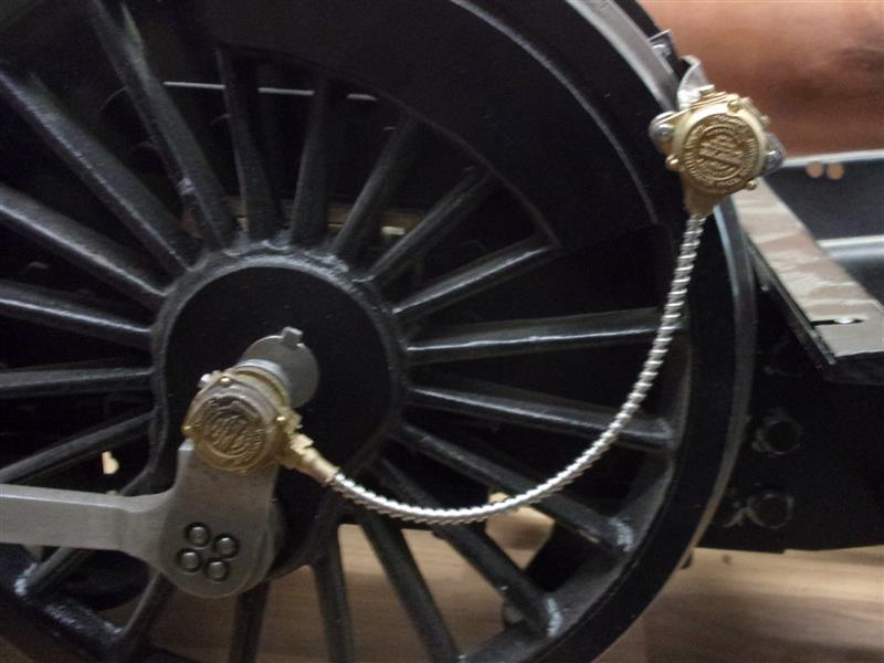
turned and the operation repeated on the other side. This last picture shows
the lefthand side where the speedo will go once I've made the bracket. And
this time, all the wheels turned nicely with only the faintest hint of binding.
A little bit of judicious polishing and some running-in time will probably
sort this so I won't do anything further at this stage. I also need to make
a pair of case-hardened pins to replace the temporary ones I used to join
the two rods. Although the bushes have this offset, once the motion is fully
assembled they cannot be seen so I am quite happy to leave this arrangement
as it is. |
 |
| 6. Connecting Rods |
|
|
 |
Using black bar throughout, I first machined
a couple of lengths of 20mm x 12mm down to 5/8" x 3/8" for the rod and the
small end on the milling machine. The big ends were made from some 50mm
x 16mm flat bar sawn to about 32mm long. These were machined on the lathe
using the 4-jaw independant chuck, facing off the back and drilling the
hole on the first operation, then facing to length, turning the spigot and
boring to size on the second op. To join the two together, I decided to
mill away a 12mm slot at half the thickness (3/16") of the bar in the the
big end piece and to make the ends of the rods to fit the slot with a tiny
amount of clearance. |
| These were then silver-soldered together and,
after cleaning up, I can see that there has been full penetration to the
other side. Moving on with the con rods, I first cleaned up the bore ready
to take the phosphor bronze collared bush that I will make later. The rods
were then clocked out on the mill and the hole for the small-end bush drilled
and reamed 5/16". The drawing shows a very precise distance between centres
for these bores and the DRO enabled me to plot this distance exactly. |
 |
 |
A pair of filing buttons, which double as clamps, were
made on the lathe to match the form of the con rod ends and a pair of simple
fixtures to enable me to do all of the machining including the tapered shape
of the rods, along with the fluting. After setting the centre of the big-end
bearing as the main datum, I chose to machine the internal forms of the
big-end oiling boss first. Stepping over by half the cutter diameter plus
half the width of the boss gave me the x-axis position of the cutter either
side of the centreline in turn. Plunge cutting in fifty thou steps, I was
able to use the filing buttons to give a clear visual indication of where
to set the final y-axis position, finishing with a full-depth outward cut
to clean the sides. |
 |
 |
I also took the opportunity to remove some of the waste
material from the other side. Using the same principle but in the y-axis
I plunge-cut the internal radii at both ends of the rods, just touching
up to the filing buttons in the x-axis. The next job was to machine the
taper on the rods and for this I first picked up on the edge of the previous
big-end cut, then adjusted the fixture at the small-end to pick up the similar
edge at this end. Changing to a smaller cutter, I machined the sides using
two passes at half-depth, where the next picture was taken, two at full
depth and a final full-depth five thou climb-milling cut to finish |
 |
 |
. I have also finished the shaping of the big-end and
have roughed out the fluting of the rods. I decided to make my own tool
for machining the flutes in the connecting rods. The drawing shows quite
a shallow runout at each end and I have chosen to make mine approximately
1.1/2" radius. The tool itself is a piece of 5/8" diameter mild steel, cross-drilled
and reamed 1/4" dia to take the tool bit and with a M5 tapped hole in the
end to clamp the tool bit. The tool bit is made from the shank of a worn-out
end mill which, coincidentally, had some locking flats already cut in. The
tool was freehand ground with 1/16" radii both sides to form the root of
the flutes. |
 |
 |
Next I set up the two fixtures to hold the rods during
machining, starting with the big-end fixture which remains static throughout
all the ops and then the small-end fixture which gets adjusted to suit the
operation. I have mounted the small-end fixture on a small angle plate which
also remains static after clamping down. Using one of the rods lightly nipped
up, I set the fixtures true in the front-to-back (y-axis) orientation. This
was followed by adjusting the top surface of the rod to be parallel to the
table ready for the first cut |
 |
 |
Then I set up the fluting tool ready for the first pass
by getting a touch on the top of the rod and then lowering the quill 1/16".
I used this method because the radius on the tool makes it difficult to
do any other way. Before starting the cut, I added some extra support around
the fixtures to help ensure rigidity, particularly the brace at the half-way
point. During cutting, it was clamped at the far end and, as the cutter
approached the middle, another clamp was added at the back and the front
one removed. |
 |
 |
For the first pass, because it was full cutter width,
I took a sixty thou depth of cut and then carefully climb-milled back to
where I wanted the start to be, not something that can be easily calculated.
Then into auto-feed and get on with something else, keeping an eye out for
when to swap the centre clamps over. The second pass was at full depth following
the same routine as before. The fixture at the small end was now adjusted
so that the lower face of the rod was parallel with the bed and the toolheight
set as before but the other way up, that i.e. the tool lifted 1/16". A full-depth
cut was taken with clamps being moved as before. |
 |
 |
The final setting on the small end fixture was to adjust
it so that the two bearing bores of the rod were parallel to the bed, the
tool lifted to the centre and a final cut in climb-milling mode and at the
same depth taken. This was to clear the witness left at the big end where
the flute width is greater. The rods are necked in by 1/32" each side in
addition to the fluting and this was done next using a 20mm end mill. I
stopped short of the end because the radius should be much greater, and
need to be eased with the dremel. |
 |
 |
The other side of the rods need machining as well and
they were mounted with some 1/8" packing at the small end to compensate
for the protruding boss at the big end. The same 20mm end mill was used
for this. After some simple deburring, this is how they look. There is still
a bit of finishing to do but the basic shape is correct. |
 |
 |
And finally a picture of one of con rods after all drilling has been finished and the bushes pushed in, assembled
to the crosshead, and a view of the whole assembly on the locomotive.
|
| 7. Return Cranks |
|
|
 |
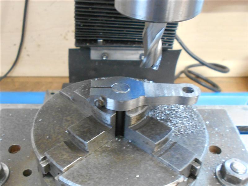
I have made the return cranks from black bar, starting
by milling to 1/4" thick and about 1" wide followed by drilling and reaming
the two holes to size. I also made a couple of filing buttons to help mark
out the form. Next, I milled away the neck section setting the angle by
eye and just nudging up to the markings. This will be dressed to the correct
shape with the Dremmel. |
 |
 |
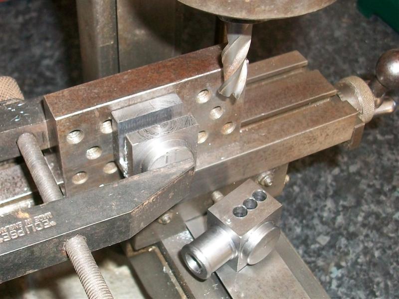
Using the filing button, the small end was linished away
and a start made on the big end. After loading to the vice using locating
dowels I set the datum as the centre of the big end hole and then indexed
along to the clamp screw hole which was drilled 6BA clear. This was followed
by spot-facing down to the correct dimension with a 10mm slot drill. Because
the return cranks are symetrical, I upended it in the vice, reset the "X"
datum and repeated on the other side. |
 |
 |
Using the same set-up, I then used a slitting saw to split
the end of the crank. Now it was time for some hand-work and the big end
form was linished and filed to shape using the larger filing button as a
guide. Once I was happy with the basic form I then set up to reduce the
thickness of the arm. To achieve this, I made use of the 3/8" reamed hole
by clamping on a piece of stock bar, planning to use this to hold the work
with. |
 |
 |
This is where a rotary table would come in useful but
I dont have one. And I couldn't put it on the lathe because the area around
the clamp screw is not removed. I do, however, have a plate-mounted chuck
which is reserved for use on the mill and this was duly mounted and the
work held as shown. Doing this in two stages, I first reduced the thickness
to the designated 7/32" using ten thou deep cuts and 2mm off the side (one
turn of the handle) until I reached the circular markings and then, by moving
the workpiece round a little in the chuck each time, nibbled away at the
circular form until I reached the linished section. |
 |
 |
To the left is a picture of the two cranks, although the
eccentric rod pin is yet to be fitted and to the right one of them temporarily
mounted on the crank pin. Once these have been correctly placed, I will
cross-drill and pin them to the crank pin. |
 |
| 8. Speedometer |
|
|
 |
I made the bracket for the speedo from 1mm mild steel
sheet but I am using the casting supplied by Adam Cro for the rest of it.
The bracket was cut at 2" x 1" and marked out for removing the side sections.
The holes were drilled first and I have made the two tapped holes 12BA instead
of 10BA because of restricted space on the casting. Then the bracket was
held edge-on in the vice and the sections removed with a 1/8" dia end mill.
|
 |
 |
The speedo head had a 1/4" hole drilled and reamed through
to match the pivot pin on the wheel. The top of the head was drilled and
tapped 12 BA and a retaining screw fitted which fits into the groove of
the pin and stops the speedo head falling off but allows it to rotate. The
other end was drilled and tapped 10BA and a stud screwed in to locate the
flexidrive pipe to. Nowadays, these castings are supplied with seven M1.0
screws to fit the covers but when I bought mine these weren't included.
I used 1/32" dia brass rivets to fix them on mine, drilling 0.8mm in the
body and 0.9mm in the covers, just in case of an alignment issue. I'm pleased
to say that the cast-in dimples are exactly matched and assembly was extremely
easy. |
 |
| 9. Next Item... |
|
|
| |
|
|