| Drawing 24 - Tender Body,
Filter, Brake, other Accessories |
| 1. Window Frames |
|
|
 |
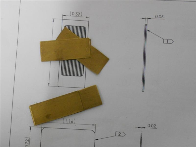
The complex shape of the window frames makes them ideal
candidates for CNC profiling but I only have manual machines available so
this was how I approached the job. Four frames are required and I started
by roughly cutting four offcuts of 16swg brass to about 2.1/8" x 1.1/4"
which I then riveted together with a couple of 1/16" countersunk rivets.
I also traced out the two windows from the drawing. The long edges of the
assembly were then milled down to 1.1/8", with both edges and one end cleaned
up, and one of the tracings with the roots of the internal radii marked
was stuck on with spray-mount adhesive. |
 |
 |
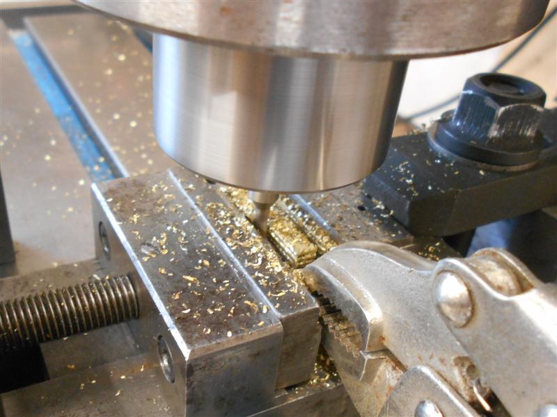
With the one true vertical edge of the window frames set
against the back of the vice, the four internal corners were picked up,
then milled through with a 1/8" slot drill followed by a 1/4" slot drill.
The 1/8" slot drill was then reloaded and the first of the joining cuts
made. One of the window corners has a radius of 13/32" and an allowance
was made for this by moving the centre-point inwards. The vice was rotated
round and the next internal edge tracked with the scriber until square,
then back in with the 1/8" slot drill to cut the channel. This was repeated
with the final two sides. |
 |
 |
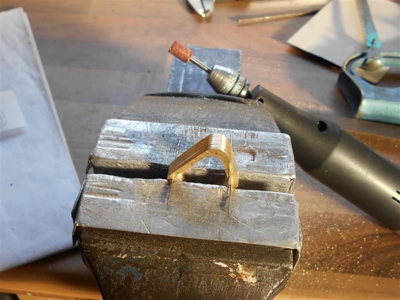
The assembly was then removed from the mill and the internal
form cleaned up using files and sanding drums. I have chosen to fix the
frames to the front panel with 1/32" brass rivets rather than solder, or
the screws that are usually employed which look way too large. Therefore
a series of 1/32" holes were drilled freehand around the periphery, trying
to be about 3/64" to 1/16" from the edge |
 |
 |
Now it was time to remove the outside waste and I started
by removing the material from the sides. To get the width of the frame somewhere
near, I set the frames on a small, thin parallel and touched on with a 12mm
slot drill to set the digital scale to zero, then used the cutter to work
down to a reading of 0.093" or 3/32". When it came to doing the end sections,
I decided to use some 1/16" brass sheet instead to get the whole lot lower
in the vice because I am milling the rivet away here and the leaves will
be unsupported. For the final edge, I used some 1/32" drills as dowels through
any visible holes. |
 |
 |
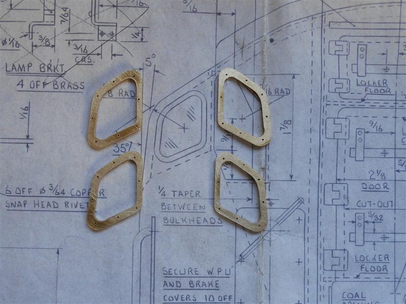
To finish, it was over to the linisher and the vice for
creating the outer radii, plus a bit more filing inside and a general tidy-up.
And, finally, here are my four window frames waiting to be riveted to the
front panel. They still need a bit more thinning out but this can be done
just prior to assembly. I haven't decided yet on which material to use for
the windows but I do have a range of acetate sheets in various thicknesses
available. |
 |
| 2. Lamp Irons |
|
|
 |
It seems that the smaller the part, the longer it takes
to produce it. The lamp irons are my own interpretation of what is correct
for the BR1 tender and have been made from some 20swg brass sheet. Four
are required for the rear of the tender and I started by cutting two strips
about 1.3/4" long and milled the width to 5/16" on the Cowells. Over on
the big mill, I made a small fixture to drop these into so that I could
accurately drill the holes for the 3/64" rivets that I shall use to fix
them with. This is a piece of 1" x 1" x 1/8" aluminium angle from the scrap
box and will be re-usable when I make the lamp irons for the front of the
loco, although the shape is a little different. |
 |
 |
After drilling, they were marked out at 3/16" and 5/16"
for the bend positions and then returned to the Cowells and the waist section
thinned to 3/16". Unfortunately, I forgot to take a picture at this point
but just some simple milling to reduce the width and working by sight to
the scribed lines. Each one was then halved with a junior hacksaw, bent
at the scribed lines and the sides and end dressed to a slight taper with
rounded ends. Also in the picture are the lifting eyes, made from 16 swg
offcuts, and the lower tank-fixing brackets from 1/2" brass angle. All these
parts will be fixed in place just prior to soldering. |
| 3. Hand Rails |
|
|
 |
As I am trying to finish the rear panel of the tender,
I decided to make the three curved hand rails next. Although I have bending
springs, they are really only any use for the steam and water pipes that
proliferate around the locomotive where accuracy of the bend is less important.
The first job was to make a simple bending tool and this was made in a similar
manner to a plumbers pipe bender, albeit a lot smaller. The two wheels are
made from 5/8" diameter mild steel with a 1/4" diameter hole through the
middle. A 1/8" wide form tool with 1/16" radius was used to form the groove,
finishing the fixed wheel a touch below 1/2" diameter and the moving one
a little larger. Others have shown how to make these and I won't go into
detail here, they are fairly simple tools to make. The wheels are mounted
between two handles, spaced to suit the 1/8" dia material, set on a large
flat plate and with a 1/8" hole to drop in a stop pin to trap the material. |
 |
 |
After a couple of trial runs to determine lengths, I made
the first pair from 1/8" dia brass tube, The idea being to tap the bore
M2.5 and, after drilling a pair of clearance holes, pull them to the rear
panel from inside prior to soldering. However, I found that my rather crude
bending tool was damaging the outside of the tube as it pulled through so
decided to make them from solid instead. This resulted in a reasonable shape
with no visible damage but left the problem of fixing them to the rear panel.
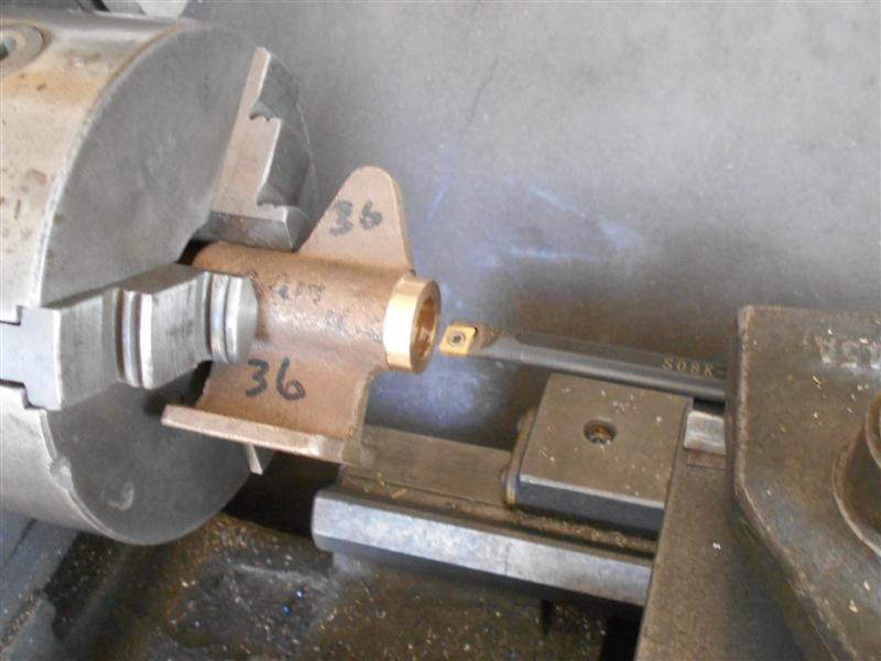
Turning a spigot on the ends was the answer, but not easy to hold in the
lathe. So I milled them instead. My boring head takes 12mm tooling and,
conveniently, I have loads of 12mm HSS end mills so one of these was loaded
to the boring head. The carbide tools that I have for my boring head are
totally unsuitable for the task in hand. |
 |
 |
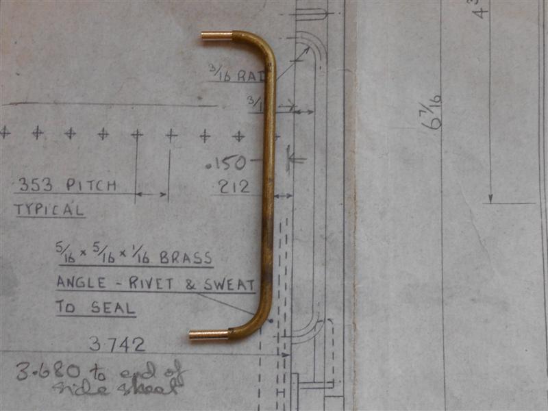
The thing to remember is that the cutter in not rotating
as in CNC milling but actually acting similar to a turning tool. Therefore,
the "centre height" has to be set by adjusting the cutter in the boring
head. Also, it is facing the wrong way and the mill has to be run in reverse
to mimic the action of a lathe. This next picture shows the cutter as it
is rotating about the workpiece, hence the ghostly image, but shows the
cutting in action. And here is the first of the handrails machined. I have
reduced the diameter of the material to 2.5mm and will drill holes to suit
in the rear panel, followed by soldering into place from the inside. The
surplus material of the spigot can be trimmed afterwards, or left as is,
there is only water space on the other side. |
 |
| 4. Ladder |
|
|
 |
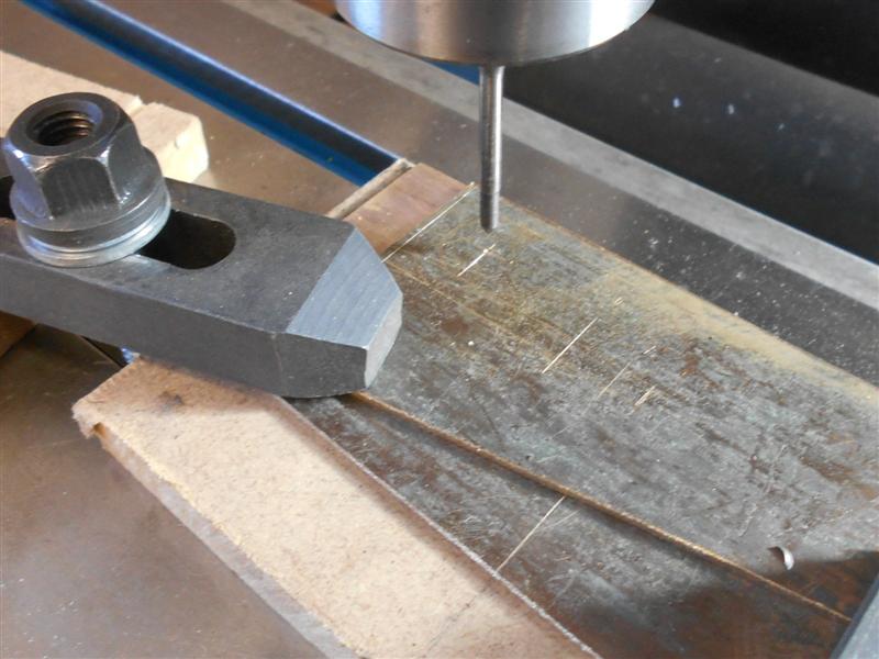
I have made the ladder rails for the rear of the tender
from offcuts of the 16 swg brass sheet. To get started I marked out the
shape of the rails, which are 3/16" wide, using the vernier height gauge
to scribe the lines on a single piece of material. I also marked the centre
of the curving section with a dot punch and used a compass to scribe the
curves. Although I will use the DRO to set cutter positions the markings,
which are not very clear on the photo but easily seen on the machine, will
only be used to confirm my postions are correct and any final hand-work.
The returning section of each rail, the part that sits on the top of the
tender, was extended by 3/8" to allow for the bending of the mounting feet.
|
 |
 |
This and another piece of material were stacked on top
of a piece of MDF and the three items clamped square to the bed using the
tee-slot packers for a quick alignment. The long outer edge of the rails
were set as the "Y" datum and the centre of the curved section was picked
up with a point and zeroed followed by plunge-milling with a range of cutters
to arrive at the final size of 5/8". |
 |
 |
A series of 3/64" holes were drilled to take the rungs
and a larger hole drilled in the extended section for fixing to the tender
top plate after bending. When drilling into MDF, the hole is always tighter
than the drill size because the MDF deforms away from the drill and springs
back afterwards. Because of this I was able to press 3/64" rivets into each
hole as they were drilled and the rivet was held firm in the MDF. Changing
over to a 1/8" slot drill, I then milled along the inside edge of the ladder
rails until I reached the 5/8" dia hole. The cutter was set about fifteen
thou into the MDF and the rivets held the material firm enough that no further
clamping was required. |
 |
 |
On reaching the X0 datum, I wound across to the other
side and continued cutting the edges of the rails. The next picture shows
the tool path that I took to free the rails from the raw stock. After releasing
the parts from the mill table, there was a small amount of hand-work to
form the outside radius with files and sanding drums. I have also drilled
another hole in the bottom of each rail to mount an angle bracket for fixing
to the soleplate. This feature is not clear on the drawing and missing in
all but the plan view, nor is it dimensioned. I have made a pair of mounting
feet from some 1/4" brass angle. |
 |
 |
At this point, I realised I had made an error and decided
to instigate "Plan B". I had forgotten to allow for the thickness of the
material when marking out and drilling the top mounting feet. So I cut them
off level with the top of the tank and turned the offcuts into angles instead.
Also seen in the picture above are the rungs which are made from 3/32" dia
brass with spigots turned to 3/64" dia at each end. The mounting feet were
riveted on first. Then the rungs were assembled between the rails, held
in place by elastic bands, and the spigots were gently peened into the countersinks
on the outer sides of the rails. To complete, rivets were soldered into
both the top and bottom mounting feet. These protrude about 3/16" below
the feet and have been rounded off with a file. |
 |
| 5. Foot Rests |
|
|
 |
The tender footrests have been made from offcuts of 16
swg brass and soldered together with high-temperature silver-bearing solder.
This melts at a higher temperature than ordinary 60:40 solder but still
way below silver soldering. Two pieces were cut 5/8" wide x 4" long for
the outer sides and were milled all round to clean up. A former was made
from 20mm MDF and milled to 1.5/8" wide and the corners rounded off. The
two brass strips were formed around the block ... |
 |
 |
...and then teased to the correct shape freehand with a rubber mallet.
To get the angle to match the top of the tank sides, the tilting vice
was set to 20 degrees. This is not the exact angle but close enough as
a starting point.
|
 |
 |
The components were then loaded to the vice and milled
all round, leaving the front edge at 9/16" high. The footplates were then
made to suit each one and soldered into place. This was to enable holding
in the vice for the next operation. |
 |
 |
These were then taken back to the mill and the cutaway
at the front of the footrests made with a 1/4" dia end mill. Britannia was
Eastern region and the cutaway differs from the Western region version.
To represent the chequered plate, I have made my own by lightly punching
indents into some four thou brass shimstock, using some imperial graph paper
as a guide. |
 |
 |
I was going to solder the assemblies direct to the tank
sides but realised that painting would be rather difficult in the space
below the footrests. Therefore, I decided to solder a pair of countersunk
screws to them with a matching pair of holes in the tank sides, the idea
being to do most of the painting first and then bolting the footrests on
for the final coat. The screws were soldered in first, followed by the chequer
plate, using low melting-point solder. |
 |
 |
The final three photos are of them cleaned up and bolted
into place, plus an overview of the tender to date. The lower edges have
been filed back to match the profile of the tank top. |
 |
| 6. Filter Box Packers |
|
|
 |
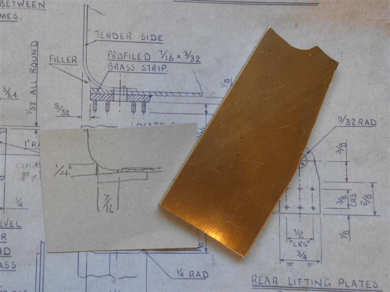
The filter boxes for the tender are mounted below the
curved sides of the tank and this requires some form of packing to be made.
The drawing shows a simple packing piece and further filling done with another
material - solder, isopon, whatever - and then smoothed. I decided to see
if I could make all-in-one packing pieces from brass and do away with the
subsequent messy filling. In the end, I made them from two parts but only
because I didn't have any suitable material available. The drawing shows
the filter boxes to be 2" long but I am using Adam
Cro's components and they measure a true-to-scale 1.7/8". Playing around
with rules and straight-edges, I calculated that the packing pieces need
to be made from 7/16" x 1/4" x 1.7/8" long. Therefore, a lump of 2" x 1/4"
flat brass bar would have been just the ticket but, unfortunately, I didn't
have any. Some 3/16" plate came in handy, though. After cleaning up to a
tad over 1.7/8" and squared off, I next set up my boring head. |
 |
 |
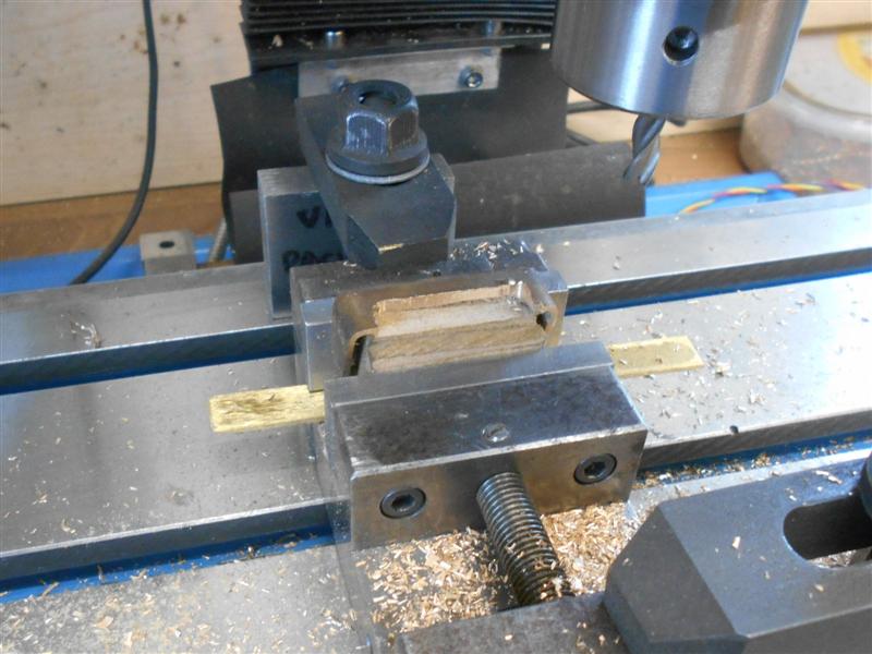
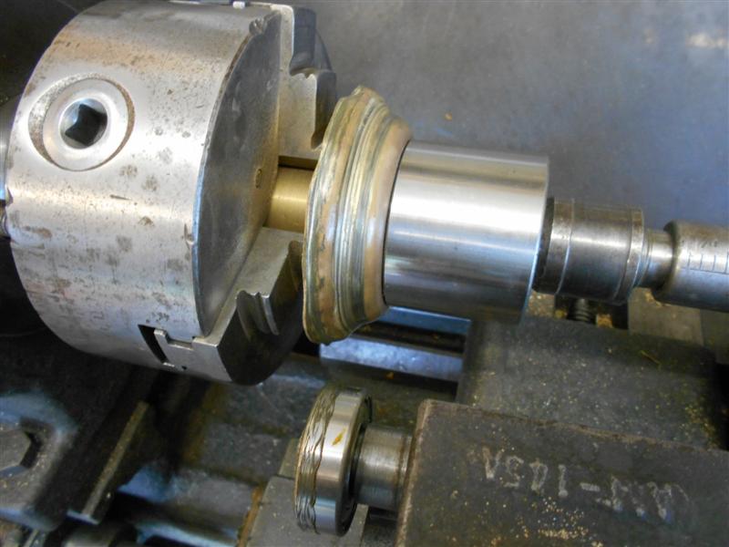
The internal radius of the tank bend is 1/2" and the
tank is made from 1/16" material, so the boring head was set to cut 1.1/8"
diameter. Next, the workpiece was loaded to the vice and some exploratory
cuts made to determine where to set the centre of the boring head. Just
touching the end and moving 7/16" along the "X" axis is not sufficient because
we are refering to an arc here. The final cut left a feather-edge to the
right and the witness 7/16" inboard, thus proving that I had, at least,
managed to get the dimensions correct. |
 |
 |
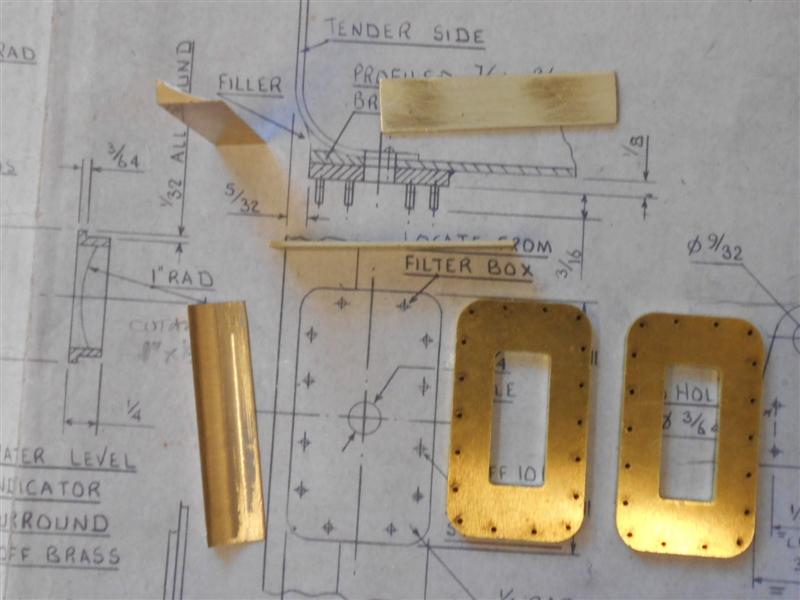
The material was then turned upright in the vice and a
slitting saw used to cut off at 7/16" width. Hacksawing and final machining
was not an option here as holding the workpiece would be extremely difficult.
And because I didn't have any 1/4" thick material available, a pair of 18swg
infill packers were made to fit between the shaped part and the mounting
rim which comes in the kit supplied by Adam. |
 |
 |
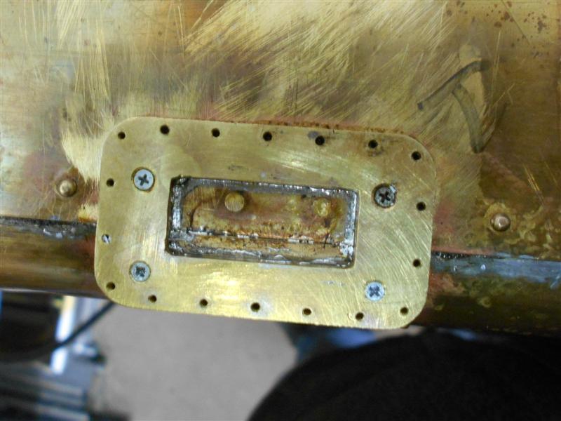
These parts were brought together with a couple of M1.6
countersunk screws and soldered. Once they became a single unit, I offered
them up to the tank and marked out another pair of fixings to hold them
in place using another pair of M1.6 screws while soldering to the tank.
A tiny amount of solder has capillaried up one of the holes but I was able
to clean this out quite easily. My little tapping fixture has been a godsend,
this time by turning the head round to overhang the base. Tapping the tank
could have been fraught with danger but I'm tapping these tiny threads with
full confidence now. To complete these parts, I have drilled the water feed
holes into the tank. A pair of blanking gaskets have been made, the filter
boxes bolted on and the tank tested for water-tightness. No leaks after
twenty four hours so the solder has successfully sealed the mounting plate. |
 |
| 7. Overflow pipe |
|
|
 |
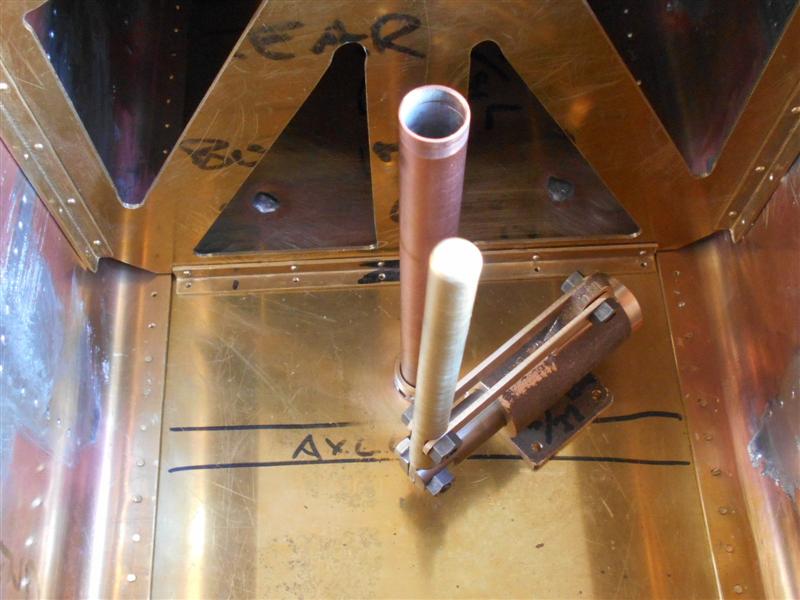
The drawing shows the overflow pipe to be 3/4" diameter
and permanently fixed above the scoop but I decided to make mine removable.
Also, because I am not modeling the scoop, I didn't have to worry too much
about how it fitted. The fag-packet sketch to the left shows what I came
up with. First, I opted to use standard 15mm copper pipe because it's readily
available (and I have loads of it, anyway) and, second, you can't get better
than a bayonet fitting for quick assembly or disassembly. The body was made
from some 1" dia brass, turned down to 22mm and then reduced at the front
to 19mm. The hole was drilled and core-drilled straight through at 19/32"
diameter and a 2.5mm wide undercut put in before moving to the mill. I have
a four-flute 19/32" core drill but a reamer could be used instead. |
 |
 |
The bayonet slots were made on the mill using my rotary
table mounted vertically as were the four drain holes around the base. The
copper tube was drilled through 1/8" diameter and a piece of 1/8" brass
soldered in to become the bayonet lugs. Although I have a selection of "O"
rings, I dismantled a standard 15mm brass push-fit stop-end and pinched
the "O" ring from there. After milling, the workpiece was taken back to
the lathe and parted off. The body was soldered into a hole in the sole
plate and the whole thing was then complete. When the tube is pushed into
the body, it passes the "O" ring, which is below the sole plate forming
the seal, and stops flush with the base of the body. The four drain holes
are level with the sole plate and allow for complete draining of the tank
when the pipe is removed. Hopefully, it should all work as planned. |
 |
| 8. Hand Pump |
|
|
 |
I have no drawing for the hand pump but a quick look
on the Reeves site produced a couple of examples to give me a start. The
casting I have has a 1/2" cast-in bore. The first job was to get the bore
machined to size and the end faced off. I also chose to turn a register
on the front of the barrel and this was done first, followed by boring to
within a few thou of 9/16" diameter and reaming to final size. The casting
was then turned around and held on the register to enable me to face the
opposite end. I then made a mandrel from some 3/4" diameter mild steel to
allow me to hold the casting on the mill for the next operations. After
squaring everything up, the mounting foot was machined first and then the
edges dressed with an end mill. |
 |
 |
The mounting holes were drilled and tapped in the foot,
a pitch of 1.1/16" between holes being chosen. The pump body was then rotated
round 90 degrees and the fulcrum machined until cleaned up, and a further
twenty thou taken off. Then it was turned through 180 degrees and the opposite
side machined to the same settings, The pivot hole was also drilled and
reamed 3/16" at this time. Back on the lathe, I made the pump piston from
some 5/8" dia stainless steel, turning this down to a bare 9/16" dia. An
"O" ring groove was put in and the piston parted off just over 2.1/2" long.
This was then taken to the mill and a 1/8" wide slot machined with a slitting
saw to take the handle |
 |
 |
Flats were also machined either side and a cross-hole
drilled and reamed 3/16" dia. Staying on the mill, the handle was made from
3/8" dia brass with flats and cross-holes machined, as before. The pivot
arms were made from offcuts of 16 swg brass, milled to 3/8" wide and holes
drilled and reamed at 2.7/16" centres. |
 |
 |
For the time being, it is all assembled with 2BA nuts
and bolts but the picture also shows a short length of 3/16" dia stainless
steel and this will make the pivot pins when the pump is proven to work.
I shall mount it in the tender in the manner shown. The handle is currently
in the middle, upright position and the diagonal mounting allows the driver
maximum handspace when operating the pump. I may, however, put it the other
way to make it easier for right-handed people. |
 |
| 9. Hand Pump Valve |
|
|
 |
The body of the handpump valve has been made from 5/8"
diameter brass and the top and bottom nuts from 1/2" hexagon brass. There
is a boss that fits into the end of the pump body and this was the first
part to be made. The round bar was held in a milling vice and the end milled
with a 5/8" end mill to match the body of the valve. Then the bar was taken
to the lathe, the 1/8" long register was machined and the piece then parted
off. Actually, my endmill has been reground and the diameter was a little
below nominal size. To ensure a good fit, the 5/8" diameter bar was rubbed
down until the boss fitted and then the boss was soldered into place. |
 |
 |
After this, the valve body was parted off at 2"long and
the bottom section machined starting with drilling at 8.5mm dia for 1/2",
then 3/16" dia to the centre point and finally tapping 3/8" x 32tpi for
5/16" of thread. The valve body was then reversed in the chuck and the other
end machined, almost identical to the lower section but with a flat-bottomed
hole for seating the ball. A spare drill was hand-ground for this. The valve
body was then taken to the mill and the cross-hole through the boss drilled
3/16" dia to meet the core. Top and bottom fittings were also made at this
time and a pair of 1/4" dia balls salvaged from a damaged ballrace. |
 |
 |
The body of the valve was then soldered to the pump body,
the clamp ensuring that the earlier soldering didn't come apart. After cleaning
everything up, I assembled all the parts and tested the pump in a bowl of
water and am pleased to say that the pump worked well, the trick being to
use a slow, steady pumping action. I filled a coffee mug in about thirty
seconds. Now proven to work, the pivot screws have been replaced with stainless
steel pins, and some stainless steel balls are on order to replace the steel
ones from the ballrace. After a final clean-up, here is the finished article.
And I hope it's never needed, but we say that about car seat belts too.
The solder used for this work was Harris Staybrite which is a silver-bearing
solder and much stronger than ordinary lead-tin solder. |
 |
| 10. Platform Rails |
|
|
 |
I've made the stanchions from 1/4" dia brass bar and the
rails from 1/8" brass bar. To start, I formed the 6BA thread on the base
of the stanchions and then parted them off to a few thou over finished length.
Eight were needed so I made ten, just in case of a second-op mishap. Next,
I made a one-inch long 6BA-threaded split sleeeve from some 5/16" brass,
drilling right through and tapping about 3/8" in from each end. The sleeve
then had two slots hacksawed part-way through with a junior hacksaw and
a third slot sawn completely through. A short 6BA bolt was screwed into
the back end to support the sleeve and a backstop set up on the lathe for
the sleeve to sit against. |
 |
 |
Each stanchion in turn was screwed into the
front of the sleeve and held in the chuck so that the angled lower section
could be formed with a plunge tool. The picture shows the plunge cut already
made. When all ten were done, they were then reloaded and the 7/32" dia
ball section formed with home-made form tool. Although it is usual to slow
things down when doing plunge cuts of this nature, this is one of those
times when high speed is an asset and I was running at my top speed of 1200
rpm. I also supported the back of the work with a piece of flat brass plate
after being a bit too heavy-handed and snapping the thread on my second
one. There was a few thou runout due to loading on the thread but it won't
be a problem on this job. |
 |
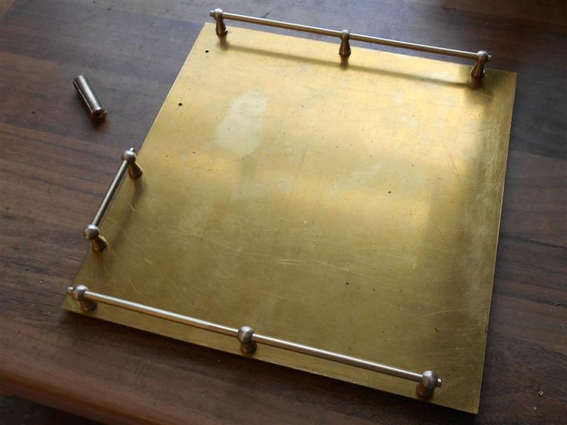
To finish these off, I set up a small vice on the mill
and, using the same sleeve as before, put the 1/8" diameter hole through
the ball using a 1/8" slot drill. Again, I added extra support for the workpiece
by using wedges and some MDF. The rails were hacksawed to length, the ends
linished and the O/D given a slight rubdown with fine emery cloth in the
lathe - the bar was about a thou oversize as drawn. The final picture shows
the stanchions fitted to the removable top plate. |
 |
| 11. Scoop Dome |
|
|
 |
After many fruitless hours searching, I have not been
able to find anything suitable for making the water-scoop cover / dome other
than castings from one of the standard suppliers. I have also wandered the
aisles of the DIY stores, supermarkets and other places hoping to find something
that could be utilised - paint can cap, camping cup, baking tin, bicycle
bell - you name it, I've tried to find it! I decided to try and spin my
own and started with a piece of 20swg brass sheet which I hacksawed and
linished to just over the calculated maximum O/D. I then made a former from
some 20mm MDF which I screwed to a billet held in the chuck. I have an old,
blunt-nosed live centre that I use with various bearing in situations like
this. |
 |
 |
After trapping the material between the former and the
bearing, then adjusting the runout and applying final pressure, I used a
broom handle to start the process of bending the metal. After getting about
ten degrees of movement, I removed the workpiece and annealed it because
it was work-hardening very quickly. After numerous re-works and annealings,
I then changed to using a bearing to continue forming the shape but it was
getting harder and harder to create the shape, with wrinkles appearing at
the periphery. Eventually, I managed to get most of the way round but the
outer section started to break away, it needed even more annealing. At this
point, I decided to call it a day and cut off wherever I could for a clean
finish. |
 |
 |
It's a bit rough and ready, and looks like a year-one
student ash tray but the basic shape is there. However, it was only 7/16"
high and needed to be 9/16" so I decided to make a collar for the lower
section, and a rummage in the scrap box produced some 3/16" thick brass
plate and this was pressed into service. The dome was placed on top of the
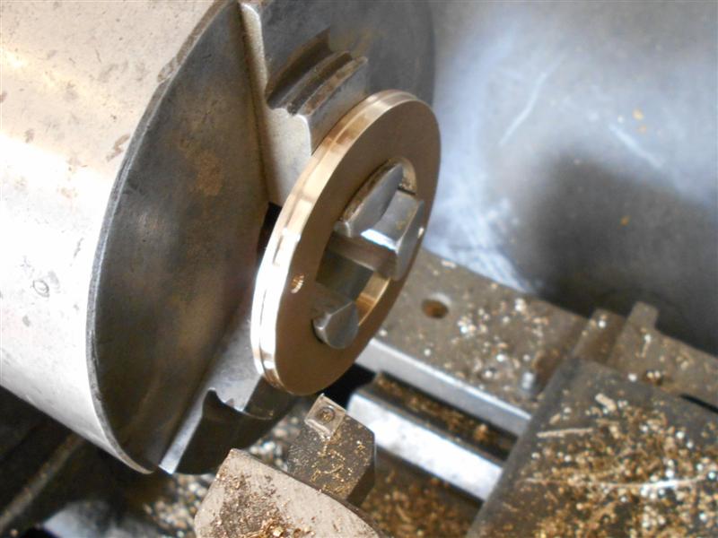
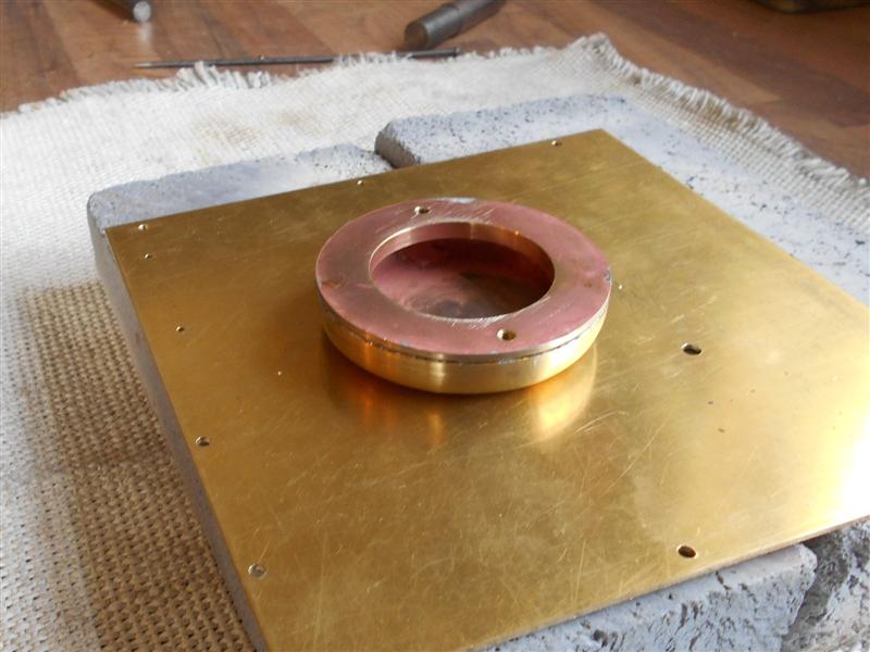
material, the diameter scribed round and the billet then set up on the mill.
The centre was found by using a point in the drill chuck to pick up the
edges of the circle and a 1.3/4" dia hole made by first using a hole saw
followed by the boring head. This was to enable subsequent holding in the
lathe. |
 |
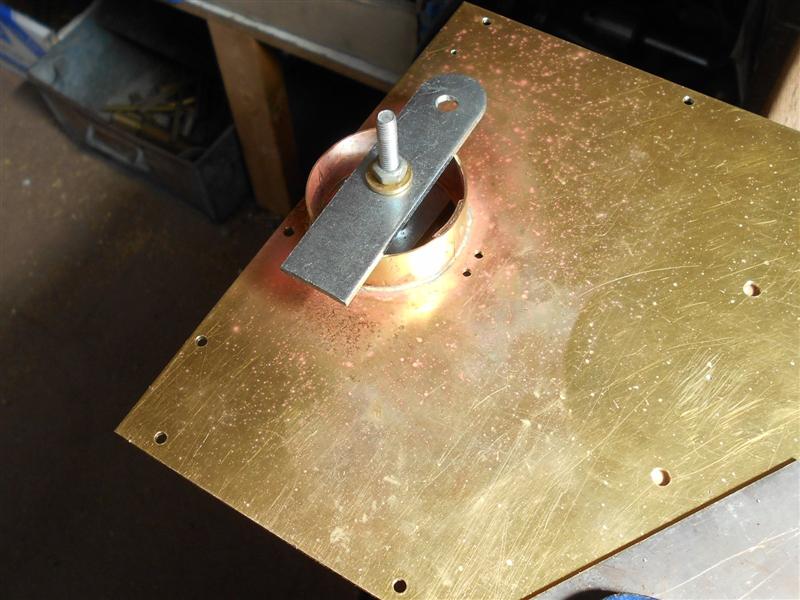
 |
Whilst on the mill, a pair of tapped holes were made for
fixing the billet to the tender platform. Over on the lathe, the billet
was machined on the O/D to set the outer size of the dome and was then reversed
and a spigot turned to take the inside of the spun component. The two parts
were then brought together and adjusted for height using a pair of screws
in the tapped holes to bear on the underside of the dome. Silver-bearing
soft solder was then used to join the two parts together. |
 |
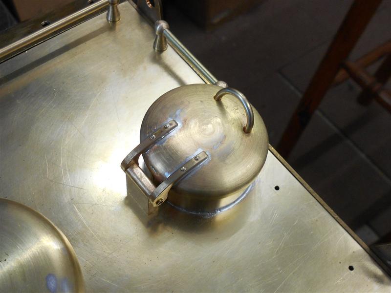
 |
I was now able to load the assembly onto the
outside of the chuck jaws on the lathe and lightly turn the O/D to the size
I wanted. After removing the solder splodges that I managed to make all
over the workpiece, I used emery cloth to clean up the outside. The assembly
was then bolted to the tender platform with brass screws with the following
result. It's not the prettiest dome ever made, nor is it particularly accurate
as regards the radius but it will do for now. At painting time, the solder
ring witness will be filled with car body filler and the gap will vanish.
Or I may have another go and see if I can do a better job with a lump of
copper from an old immersion heater tank. A decision for another time. |
| 12. Filler Hatch |
|
|
| The filler hatch at the rear of the tender platform is
shown as made from some 1.5/8" dia brass tube for the riser and the lid
made from 1.3/4" dia brass bar or from 5/16" brass plate. I had none of
these so another visit to the scrap box was needed. Since I had no brass
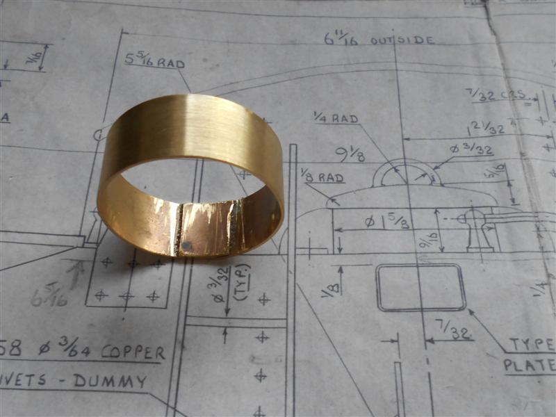
tube of the required size, I made some from an offcut of 20 swg brass sheet.
A piece was cut at 3/4" wide by 5.1/2" long and bent around a piece of 1.3/8"
dia bar freehand. By the time it had sprung back, it wasn't too far from
finished size and the ends were trimmed back and the shape re-rolled until
I had a butt-join that left a reasonably accurate diameter. It takes a lot
longer to do than to describe, much too-ing and fro-ing required to achieve
the desired result. This was soldered together with an overlay strap on
the inside. |
 |
 |
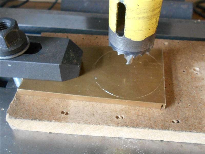
To make the lid, I started with a couple of offcuts of
3/16" brass plate and the first piece was loaded to the mill and a 1.1/8"
dia hole put in using a hole-saw followed by the boring head. This was to
enable holding on the outside of the chuck jaws, my 4-jaw s/c being the
smallest.This was then roughly cut and soldered to another piece. |
 |
 |
This was then turned to 1.3/4" dia and the face lightly
skimmed to true it up. Soft jaws were now loaded to the chuck and bored
to suit the workpiece, followed by facing the front of the workpiece to
5/16" long. A 1/16" deep recess was then formed at 1.5/8" diameter to allow
the tube to lightly clip in. |
 |
 |
This brings the underside of the filler lid to the 9/16"
height given on the drawing. The workpiece was then reversed in the soft
jaws and the 1/8" radius formed at the edge of the lid using a hand-ground
form tool. |
 |
 |
Another form tool was used to form the large radius of
the lid top. This took quite a bit of time, moving the angle of the tool
back and forth to suit until I had the desired result. After a quick polish,
the item was placed on the tender platform to check that it looked in scale. |
 |
 |
I made the lifting handle from a length of 3/32" dia brass
rod, simply bending it around a piece of 1/2" diameter bar. The anvil underneath
the 1/2" rod is a small two-way vee-block and the cross-way comes in useful
for simple bending jobs like this. I then set up a chuck on the mill and
drilled a pair of 3/32" diameter holes in the lid to take the handle. I
also put in a couple of dimples either side to help line up the hinge straps.
The drawing shows the handle set square to the angle of the lid but I just
drilled square to the table and bent the handle to the correct angle after
assembly. |
 |
 |
Once pressed in to depth over a piece of 1/4" dia rod,
a dab of solder was applied to the underside and the bend put in. The hinge
bracket is made from an offcut of 3/16" brass plate with a hingepin hole
drilled at the top and a pair of 8BA fixing holes in the base. The hingepin
is a piece of 3/32" dia brass tube and the hinge straps are made from some
1/8" brass strip thinned to 3/32" and hand-filed to size and shape. I drilled
a pair of 1/32" holes in the tops of each of the straps, then spotted through
to the lid and drilled four holes here also. I then used some 1/32" brass
rivets to hold the hinges in place on the lid prior to soldering. This is
not a feature of the BR standard tenders but I like the look of them so
they will stay after soldering, rather than filing them down after their
work is done. I have cut the hinge pin 1/32" longer then the outside dimension
of the hinges and flared the ends slightly by inserting a lathe dead-centre
and giving a gentle tap. |
 |
 |
The final jobs were to make a large hole in the top plate
and to solder the filler tube in place. I was concerned that heating the
tube would cause my earlier work to fall apart so a pair of 1/16" holes
were drilled through the tube and strap. Countersunk brass rivets were then
used to act as a mechanical fixing. The lid assembly was bolted to the top
plate using 8BA brass screws into the hinge bracket and the filler tube
placed underneath. This was then scribed round as a guide for the filling
hole. Once drilled and bored, the tube was clamped in place and soldered.
The position wasn't perfect and I had to elongate the hinge-block holes
in the top plate but the lid now closes down in just the right place. I
can fill the tank easily enough although, with a removable top plate, drilling
the hole was probably a waste of effort. |
 |
| 13. Water Filters |
|
|
 |
I've chosen to use the tender filter boxes supplied by
Adam Cro for my project and they come as a complete set of castings with
a small amount of machining to do. Nuts and bolts are not supplied, nor
is the material to make the valves and seats, but a couple of lengths of
"O" ring cord are thoughtfully included to assist sealing the filter box
to the mounting plate and also some gasket material for the bottom cover
along with the filter components. The mounting plates are pre-drilled with
the holes for the filter box mounting studs and need a small amount of fettling
around the edges as well as tapping but are otherwise finished. The various
hole positions on the main casting are pre-dimpled but Adam advises to ignore
the top face dimples due to a slight misalignment and, instead, spot through
from the mounting plate.
|
| I started by carefully checking over the casting
and found that the depth of the "O" ring channel in the top of the main
casting was 1.5mm and the "O" ring cord supplied is 1mm diameter, thus leaving
just over half a millimeter to clean away from the top face. After fettling
the sprue witness from the edge of the casting, I checked how parallel the
sides of the boxes were and found a slight taper, making it a little more
difficult to hold in the milling vice. To get around this, I wrapped a couple
of turns of insulating tape around the body which gives a slight cushioning
effect but still allowed mounting in the vice. |
 |
 |
The tops of my vice jaws are parallel with the table within
tenths of a thou so I was able to rest the flanges on a pair of small parallels
but I also wrapped a turn of tape around these packers to ensure they didn't
vibrate loose and fall out during cutting. A couple of 10 thou passes running
round with a 12mm dia end mill brought them to size, but I could feel the
slight abrasiveness of the material on the cutter. It's silicon bronze and
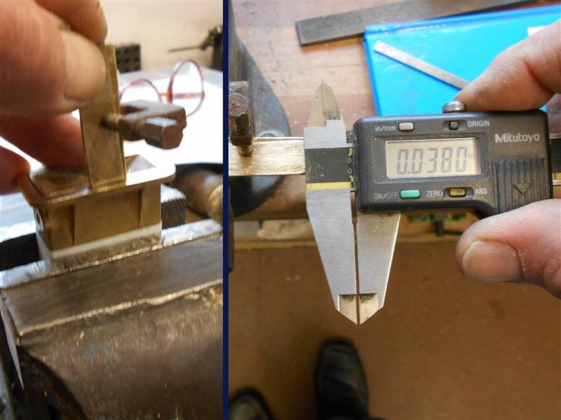
I would recommend using a sharp new cutter for this. A little tip for any
who may be unsure about how to measure the depth of narrow grooves. Use
a couple of pieces of thin brass sheet, one down the slot and one resting
on top, clamp them together and use the step-measurement function of your
caliper to get the depth. |
 |
 |
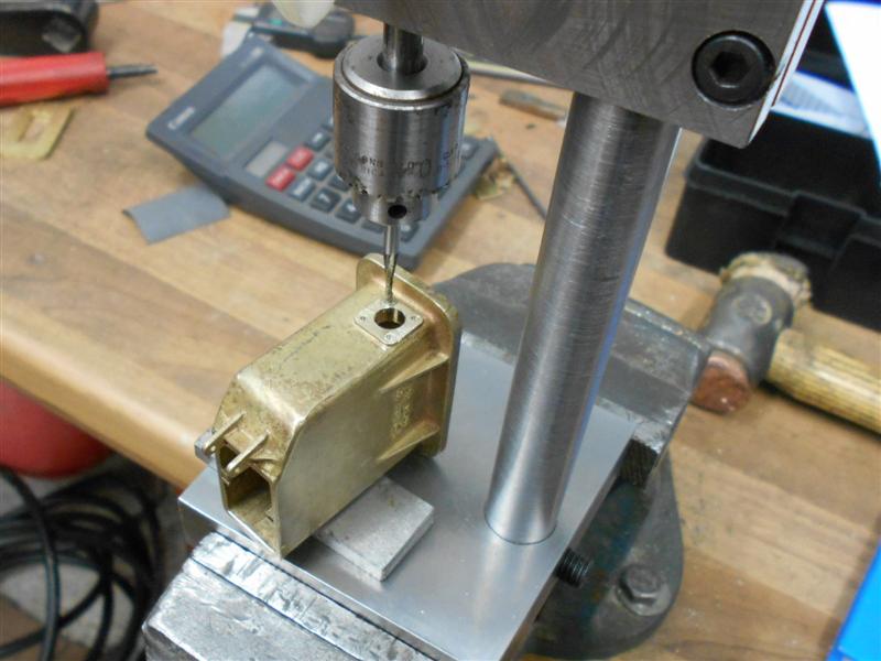
Having this machined face made it relatively simple to
hold for subsequent machining operations and the first of these was to clean
up the bottom face to allow the lid to seal. One of my general-purpose milling
fixtures came in useful here, allowing me to clamp on the underside of the
flanges. It only needed a few thou to clean up, and I changed to a 1/4"
dia cutter here. Care needs to be taken as one approaches the hinge section.
The fixture was then repositioned and another pair of clamping holes drilled
and tapped so that I could hold the filter box vertically, using a square
to get it upright. A light skim was taken across the face of the outlet
pipe flange mounting point and it says much for the quality of these castings
that my five thou depth of cut was more than enough to clean up. |
 |
 |
I also chose to centre-drill and drill the three 12BA
holes, rather than rely on the dimples, so the outermost dimple was picked
up with a point and the DRO zeroed, then offset by half the PCD and re-zeroed.
The outlet hole was cleared with a 3/16" slot drill and, using the bolt
hole circle formulae, a light touch with the centre-drill at each bolt hole
showed that the dimples were exactly where they should be. Based on this,
it would be possible to just clean the flange mounting point with a fine
file and drill directly into the dimples with confidence. The holes were
drilled 1.1mm, slightly over the book size, and left for tapping later.
Care needs to be taken on the outermost hole as the centreline is level
with the outside face of the casting. The other side was treated in a similar
fashion, a 3/16" dia slot drill clearing the hole and then plunging through
the inner wall to create the internal valve seating point. The outer wall
was then opened up with a 6mm end mill to take the water valve body. |
 |
 |
To finish the filter boxes, the lower hinge brackets and
locking clamp brackets were drilled freehand using the cast-in dimples.
I have chosen to drill 12BA clear on the front bracket and tap 12BA on the
rear bracket and will use a 12BA bolt screwed in from the front and a 12BA
locknut on the rear. The various holes were tapped on my new tapping fixture.
The pre-drilled holes in the mounting plates were redrilled at 1.1mm and
paired with their respective boxes, clamped to them and spotted through.
The boxes were then drilled 1.4mm and the plates tapped 12BA. Adam has kindly
consented to me photographing the work sitting on the drawings, as is my
normal practice. |
 |
| 14. Filter Box Fittings |
|
|
 |
Some of the parts that comprise the filter box assembly
come provided and most of these need minimal work. Other parts need to be
made and, so far, I've found the drawings to be accurate, complete and reasonably
well laid out making the job relatively painless. Unless you are like me,
that is, I managed to make hard work of the water outlet fittings. I started
by holding on the boss of the flange with the work tight to the jaws and
facing off to the finished dimension. Next I centre-drilled and drilled
through 11/64" which removed the stub on the back, the intention being to
ream 3/16" later. A tiny boring bar was used to create the "O" ring recess,
care being taked on the outer diameter as there's not a lot of wall thickness
left here. Next, I put the 3-jaw on the mill and set up to drill the mounting
holes. By setting one chuck jaw square to the table, I was able to locate
the bolt hole positions over the jaw gaps and drill straight through using
the dimensions given. |
 |
 |
By this point, I'd already worked out that I had made
life hard for myself and now had to bolt them to the filter box and use
this as a simple fixture to size the water outlet hole. Of the other cast
parts, the bottom cover just needs the sprue removed and the holes for the
locking bar drilled. The locking bar needs two holes drilled and the locking
handle needs to be drilled and tapped. All these items are dimpled and very
easy to finish |
 |
 |
I have also made the swing bolt that holds the lower cover
in place. Starting with a piece of 3/16" brass rod, the diameter was reduced
to 0.067" for about 3/8" and a 10BA thread cut. This was then parted off
with an overall length of 5/8". The eye was made next by milling some of
the material away on each side and finished at 0.075" thick x 0.110" wide.
Finally, a 1.4mm cross-hole was drilled to enable a 12BA bolt to pass through
and the eye was rounded off with files. |
 |
 |
The flange section has been made from 5/8" diameter brass
bar and the 6mm spigot turned for a good fit to the reamed hole in the filter
box. The 1/8" Whitworth thread was drilled and tapped and the items parted
off. They were then taken to the mill where the four bolt holes were drilled
1.4mm and the square outer form machined. I also put the tiny recess in
the flange using a 4mm end mill. I am not putting the "O" ring groove in
the boss and will be using some gasket material instead. The spindle is
made from an M8 stainless steel bolt and the 1/8" dia was machined first,
for about 1/2" long, followed by the 6mm dia, slightly undersize to fit
through the 6mm reamed hole in the filter box, and a 3/32" diameter by 3/32"
long section at the front for the handle. |
 |
 |
The 1/8" x 40 Whitworth thread was cut next, getting as
tight to the shoulder as possible, and finally a 1/16" parting tool was
used to first create a 0.120" diameter undercut, then a 1/32" wide x 0.160"
retaining lip, and then parted off. When assembled, there will be a 6mm
O/D x 1.5mm c/s "O" ring either side of the flange and these are what create
the seal depending on which direction the valve is turned. Unlike sand castings,
the surfaces of these filter boxes, including the internal ones, are very
smooth and the "O" ring appears to seal very well. The "O" rings in the
picture are a little bigger and will be changed. |
 |
 |
Two pairs of brass stampings are included together with
the filter gauzes and the instruction to solder these parts together and
finishing with a maximum thickness. I didn't want to take the risk of soldering
these parts and filling the gauze with solder so I made a new pair of carriers
for the gauze from some 26 swg brass sheet. These were cut out a little
over twice the required length and bent in half and squashed flat in the
bench vice with a sacrificial piece between the leaves. These were them
milled to the same width as the supplied leaves. Then they were set up on
the mill in a small vice and a 1/8" diameter pilot hole drilled in one corner. |
 |
 |
The open end of the leaves were clamped with a mole-grip
(the only thing I could find that didn't foul the workspace) to stop them
springing apart during machining and a 1/8" end mill was used to remove
the centre section. It pays to work away from the stop while the material
is at maximum strength and back towards the stop when it's most vunerable
to collapse. |
 |
 |
The parts were deburred all round and the sacrificial
centre leaf discarded, leaving a space for the gauze. Finally, they were
trimmed to length and set into the guideways in the filter boxes, a small
amount of fettling being needed to clear a couple of bumps in the channels.
If I need to change the gauze at a later date, the carrier just slides out
and the old gauze can be discarded and a replacement fitted with ease. Apart
from making the small square handles and cutting the gaskets, that is the
filter boxes completed. However, I am still doing a few small jobs on the
tank and chassis at present so will refrain from fitting the boxes until
these are complete. These boxes are highly vunerable to damage while the
tank is unmounted from the chassis. |
 |
| 15. Next Item |
|
|
| |
|
|