| Drawing 15 - Valves, Ejectors and Pipework
|
| (Marked as drg No. 21 at bottom right) |
| 1. Smokebox Ejector |
|
|
 |
The drawings offer a somewhat sparse version of an ejector
but we have to start somewhere. However, scaling from the drawing the 9/16"
width is actually 1/2" which is par for the course with these rubbish drawings.
I made a block to the dimensions given from an offcut of 1" dia brass bar
just to get the ball rolling. I decided to try and make something a little
closer to prototype and printed this picture from a blow-up of a Nigel
Fraser Ker picture. I've milled out the basic shape and drilled and
tapped holes to suit based purely on the visual aspect of the ejector. |
 |
 |
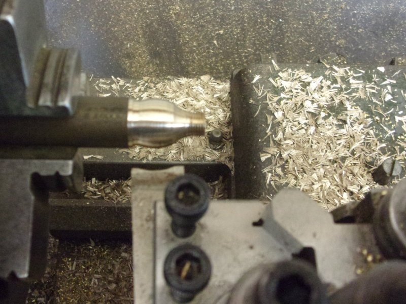
Contrary to the drawing, the pipe flange at the bottom
of the ejector is triangular, not square, and was made from some brass hexagon
material. After turning on the lathe, the triangular shape was milled and
the picture to the left shows how easy it is to make a triangle from hex
bar - just index round two flats at a time. This was then returned to the
lathe and parted off. The flange that connects the smokebox pipe to the
ejector body was made in similar fashion, although the square section was
created in the vertical mode instead. After finding the centre, it's simply
a case of winding round at the same x-y reading, just plus or minus to suit.
The central hole is for a 6BA screw to clamp it to the body. The flange
holes are 10BA. |
 |
 |
After this, it was a case of nibble a little off here,
a little off there and generally keep removing material to leave a similar
shape to the photo. There are no dimensions, everything just done visually.
Once the various screws were in it started to look more the part. The bit
to the side was made next but, not knowing anything about ejectors, I've
no idea of what to call it! The front end was turned first, taken to the
mill for the flats and flange holes to be machined, then returned to the
lathe for parting off. The M6 thread is to screw the next piece of pipe
to. |
 |
 |
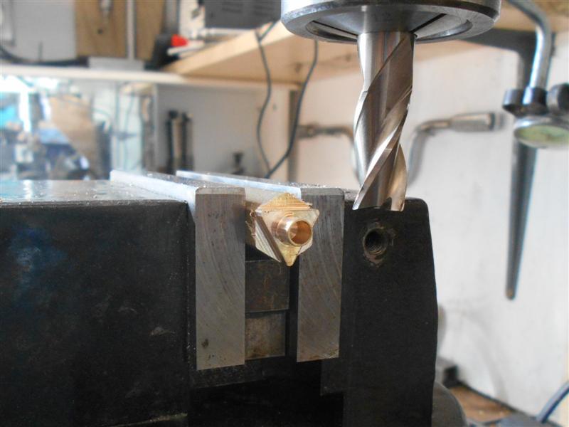
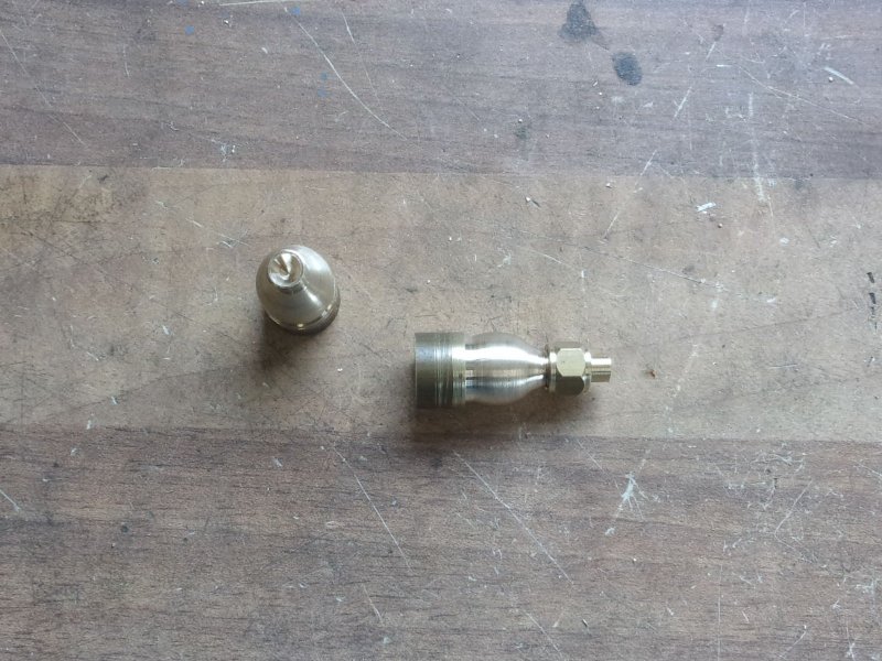
To finish the ejector, I bought an 8mm brass elbow from
Screwfix for £ 2.09 (part no 78141 if anyone else wants to get one), cut
the threads off and linished the smokebox shape on one end, flat on the
other. A short length of 1/4" bar made the joining pipe, a piece of hex
material for the left-hand nut and the crenellated nut was made from some
7/16" dia bar. A 1/16" dia end mill formed the crenells, of which I made
eight by indexing round forty five degrees at a time. The base of the ejector
was shaped on the linisher and finished using emery cloth on the smokebox
to get the radius correct. |
 |
| The mounting holes were drilled 10BA clear
and the smokebox drilled and tapped to suit. All the parts are just press-fitted
together and there is also a plug wedged into the other part of the elbow,
tapped 6BA to allow a screw to come though from the smokebox to fix it.
The various sections of pipe will be cut later, possibly substituting solid
bar depending on how easy they bend. Meanwhile, here is the assembly finished,
although I will probably spend some idle moments rounding a few more edges
and filing away some more material before it finally gets painted. |
 |
| 2. Exhaust Injector |
|
|
 |
I've looked around for a casting for the exhaust injector
but there only seems to be one on offer, a white-metal casting for about
£38 but it looks a bit squashed to me. So I've sculpted one out of some
old brass offcuts. The first part to make was the main body and for this
I used a lump of brass that my father cast in sand nearly fifty years ago.
There were loads of inclusions and it was no good for anything else. The
middle section of the injector was turned first, finishing at about half-inch
diameter, using a radius form tool to help mimic the actual casting. The
big hole is one of the sand inclusions and will be filled with stopper before
painting. |
 |
 |
Then it was turned round in the chuck, the major diameter
turned to just over 1.1/8" and a 3/4" dia spigot turned that will be the
pipe flange. Next, it was over to the mill and reduce the sides to about
9/16", leaving the flange 3/32" wide. |
 |
 |
Top and bottom were also milled to their respective sizes.
None of this is measured beyond rule-accuracy, just machined until it looked
about right. The basic shape is starting to appear. The photo I am using
throughout is a grey-scale version of one from the Nigel
Fraser Ker site, which Nigel has kindly given me permission to use. |
 |
 |
A 3/16" end mill was used to clear the underneath area
behind the flange. Then the first of the angles was machined on the top,
just aligned by eye. |
 |
 |
The photo shows a small flat area before the slope of
the other angle, so this was machined next. This front slope appears to
be a bit steeper. |
 |
 |
There is also some sort of pad on the top so this was
machined next. The three square pipe flanges were made next. The drawing
shows them as all the same size but the one on the right is smaller so I've
made two from 1/2" square brass and one from 3/8" square. There is a small
locating spigot on each to assist assembly. |
 |
 |
Because all these parts are cosmetic only, the flanges
were faced to twice the thickness to simulate both top and bottom flanges
at once. Then the were drilled for the dummy 10BA nuts and bolts. The next
part made was the thinner barrel-section at the front, a piece of 7/16"
diameter brass faced flat at the joining point and with a 6BA tapped hole
at the front. Into both this and the main body, spot-faced holes were machined
to locate the pipe flanges. |
 |
 |
A few other drilled and tapped holes were made in the
body where bits stick out or are bolted on, the six bolt holes in the main
flange drilled and the area behind this flange hacksawed and file out to
allow nuts to fit the space. Then the front barrel was silver-soldered to
the main body. The flanges have been attacked with a junior hacksaw to simulate
the join. The smaller flanges in the picture are not yet fixed, and also
on view is a lump of 3/16" brass plate shaped to suit the overflow valve
at the front. Once I was happy with the shape, I drilled and tapped a pair
of 10BA holes and one 6BA hole for the piston and lever parts. |
 |
 |
One intricate little part made was the fork in the centre,
made from 1/8" square brass, turned and threaded 10BA, then cross-drilled
with a 0.8mm drill to take a 1/32" rivet as a hinge pin. For the size of
my kit, these are seriously small sizes. This is the little valve completed.
the tiny stirrup on the left is a piece of ten thou shim screed onto a 10BA
stud. The lever is 20 swg brass filed to shape. |
 |
 |
The next couple of pictures show the valve fitted to the
barrel with a 6BA screw. There is a blind tapped hole in the back of the
body and a hole through the barrel. Two of the three flanges have also been
soft-soldered to the body. |
 |
 |
The platform for the exhaust injector was made from 16
swg brass and shaped to suit the angle of the ashpan. A pair of holes were
drilled, the idea being to use a pair of 8BA screws with spacers. Also in
the picture is a piece of brass, about 3/16" square, that screws to the
back of the assembly to simulate the boiler steam inlet. It's a good job
I managed to get the two flanges in line. Drilling the two 8BA fixing holes
in the bottom of the barrel. |
 |
 |
A slim triangle of brass was made to form the web in the
top of the injector and the platform had it's cutaway made for the overflow
pipe. The small piece of brass angle and the flat offcut bolted at each
end are the mounting feet. The little brass rectangle is the overflow flange
and the turne piece of 1/4" hex is the exhaust steam valve nut on top of
the injector. |
 |
 |
This is a view from the back showing how the two parts
are screwed on. None of this will be seen once all is assembled. And this
is the upper web soldered into place, a bit scruffy but needs filing down
somewhat. I haven't made the small front web, that's a detail too far. |
 |
 |
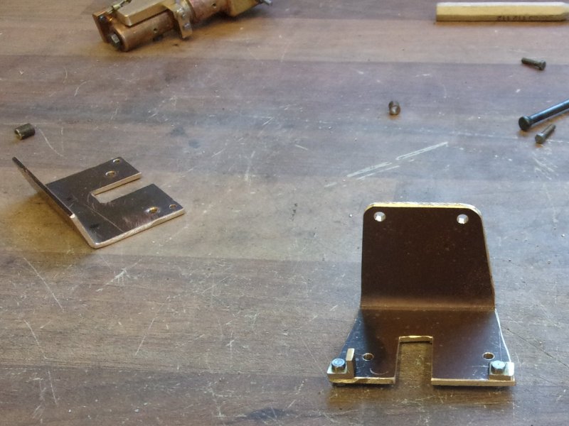
With all the screws in place, and ready to fit to the
ashpan, it became obvious that the platform was never going to hold the
injector in the correct position. The designer had made a complete pig's
ear of placement, as seen when comparing the drawing to the photo. The injector
sits below the ashpan, not above the baseline as drawn, so a new bracket
had to be made. This entailed a bracket folded in the opposite direction
with fixing screws above the injector. This is the new platform with an
acute-angled bend. |
 |
 |
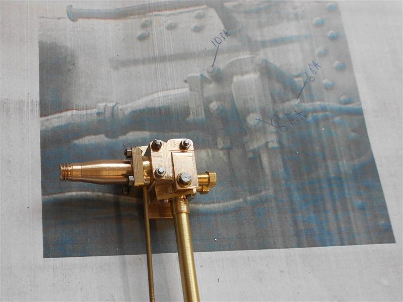
This is the injector temporarily mounted on the ashpan.
It needs tweaking slightly but is pretty-much in the correct position. The
pipes, once made, will be a light push fit into the recesses except for
the exhaust steam pipe which will have it's own flange and be bolted on.
On the right, the large pipe flange has been fitted and the overflow pipe
soldered into place. A coat of paint makes all the difference. |
 |
| 3. Washdown Valve |
|
|
 |
I've also made the dummy washdown valve from more bits
of brass offcuts and this one was very straightforward. A piece of 10 swg
for the backplate, some 3/8" x 1/2" for the body and some 16 swg brass for
the top flanges. A short length of 1/8" dia had some flats milled onto it
to make the spindle. The body had a 1/4" dia recess put in with a slot drill
and a piece of bent 1/4" dia pipe soldered into it. The thread was formed
on 5/16" dia bar with a spigot which was fitted into the pipe and soldered.
The rest was a few drilled and tapped holes and some screws. |
 |
| 4. Dummy Duplex Valve |
|
 |
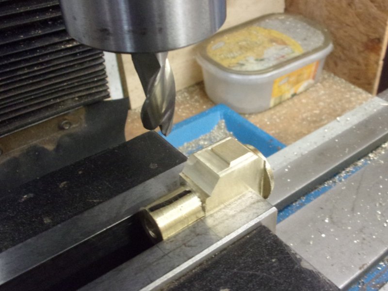
The duplex valve on the driver's side is not needed and
is used instead to feed steam to the blower valve. The drawing shows a rather
box-like construction with only a passing resemblance to the prototype.
I have tried to construct something a little more realistic-looking while
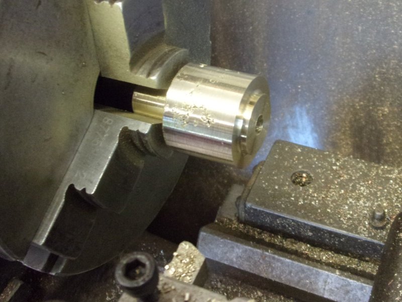
still making it a functional device. A bronze offcut was used to make the
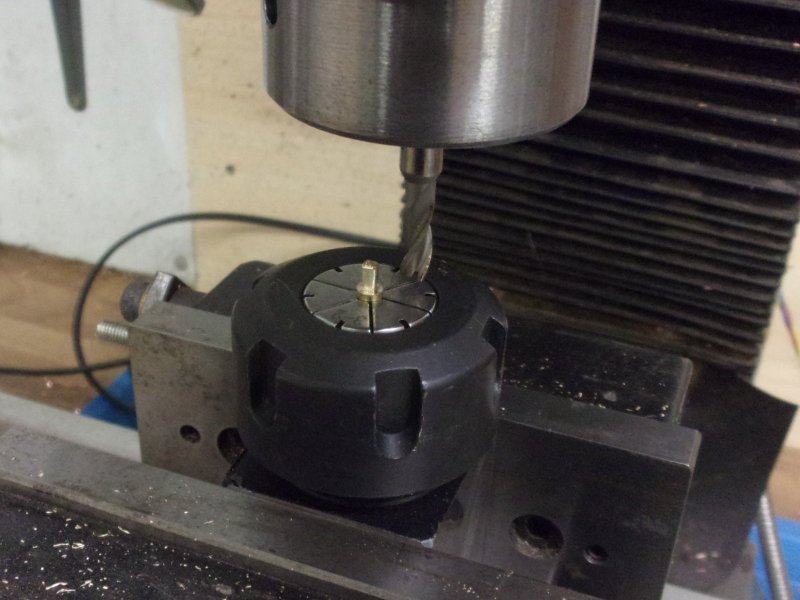
body rather than brass as this will carry live steam. After milling up a
basic block it was loaded to the independant 4-jaw chuck for machining of
the steam entry point which is offset in both planes. A 3/32" diameter hole
was drilled straight through and the front turned to create a stem with
a 1/4" x 40 tpi male thread. Over on the mill, the three mounting holes
were drilled 3/32" dia for 8BA clearance, the tipped on edge and the holes
for the valve and the steam outlet drilled, also 3/32" diameter. |
 |
 |
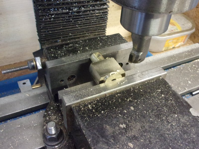
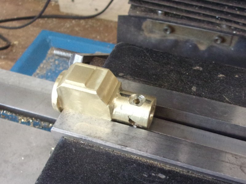
These holes were then opened up to 7/32" diameter and
tapped 1/4" x 40 tpi. A 3/16" end mill was run between the holes and round
the outer edges to create the raised bosses. The external circular form
of the bosses was created with a home-made tool set in the boring head.
This is a piece of 12mm dia mild steel drilled and reamed 3/16" to take
ground-up broken centre drills. By setting the tool up to the outer size
of the boss, it is easy to create the external circle. The inset shows the
form tool next to a standard boring tool. |
 |
 |
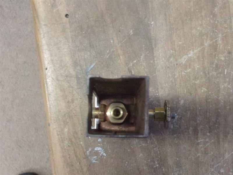
The boring head is positioned over the hole centre, all
adjustment being done directly on the boring head. This shows the first
one finished. The workpiece was then laid over onto it's side and the DRO
centred on the middle of the three mounting holes. I need to bring the valve
to the right thickness leaving a raised centre section and need to determine
the amount of material to remove. Feeler gauges were used to find the distance
from the boss to the packing piece. |
 |
 |
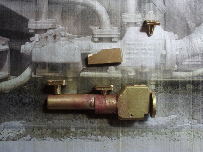
The feeler gauges were then placed on top of the boss,
the 1/4" diameter end mill rested on top and the "Z" axis readout set to
zero. This is the height of the tool for the final pass. The end mill was
then run round three sides using the hole co-ordinates as the reference
positions. Finally, two blind 6BA holes were tapped on the far side of the
block for a pair of dummy pipes to be fitted to. All the rest was handwork
with needle files. Once it is painted it should bear a passing resemblance
to the full-size valve, even though one of the outlets is missing. It certainly
looks better than what was on the drawing. |
 |
| 5. Injector Stop Valves |
|
|
 |
There are two injector steam valves on Britannia and I
have made a pair from some bronze offcuts that I had. There will be a pair
in here somewhere although I have another piece in the scrap bin and will
make an extra pair at the same time. Rather than waste this material, I
set up each operation with brass bar first, then followed with the bronze.
The first thing to make was a tool to form the neck radius of the valve
and for this, I chose to use the back end of a 1/2" diameter end mill. The
drawing is wrong (again) where it specifies 1/2" radius, it should be 1/4"
radius (1/2" diameter). |
 |
 |
As can be seen, the tool gets mounted upside down in the
toolpost holder, the angle being enough to give a bit of clearance without
losing too much of the form. The holder is set high in the toolpost and
because I want to finish at 1/4" diameter, I set the tool just a bit less
than 1/8" above the centreline of the work. |
 |
 |
This is another shot showing the tool in action. It's
also a good example of why setting tools exactly on the centreline of the
work is a nonsense. I've never used a tool-height setting gauge in my life,
always just eyeballed the height and moved it if it wasn't cutting quite
right. So here is the fully-formed curve of the valve neck ready to be threaded. |
 |
 |
To get the outer form of the globe I used a HSS tool already
in the toolbox. The diameter is nearer 7/16" than 1/2" but it's close enough
for this. The 1/4" x 40 tpi thread has already been cut with a button die.
Before they were parted off at an inch long, a centre drill with a ground-back
pilot was used to create the front form for the nipple. Here are the first
two, one with a nut and nipple attached. |
 |
 |
The next job was to create the recess for the branch of
the valve and they were held in the milling vice as shown, it not being
worth setting up a fancy holding solution to get around the differing diameters
problem. Although it can't be seen, there is a nut screwed to the front
to protect the thread from crushing. To turn the opposite end, they were
screwed into a tapped mandrel and the procedures repeated. To release them
from the mandrel, a piece of emery cloth was wrapped round the valve and
pliers used to grip. The recess for the branch came in handy here. |
 |
 |
The last job done today was to part off 1/4" lengths of
1/4" diameter brass and silver-solder them into the branch recesses. A turn
of 0.5mm silver solder wire was wrapped around each branch and the parts
held with some sacrificial clips. The threads were coated in correction
fluid for protection. This picture was taken immediately after soldering.
And here is one alongside the drawing. These will go in the pickle overnight
and I will machine the rest of the valve tomorrow. |
 |
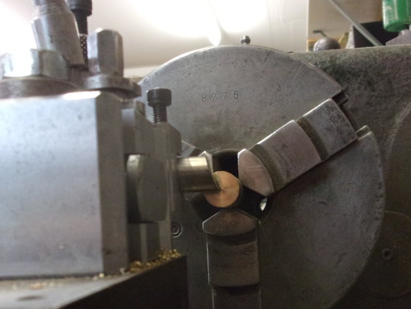
 |
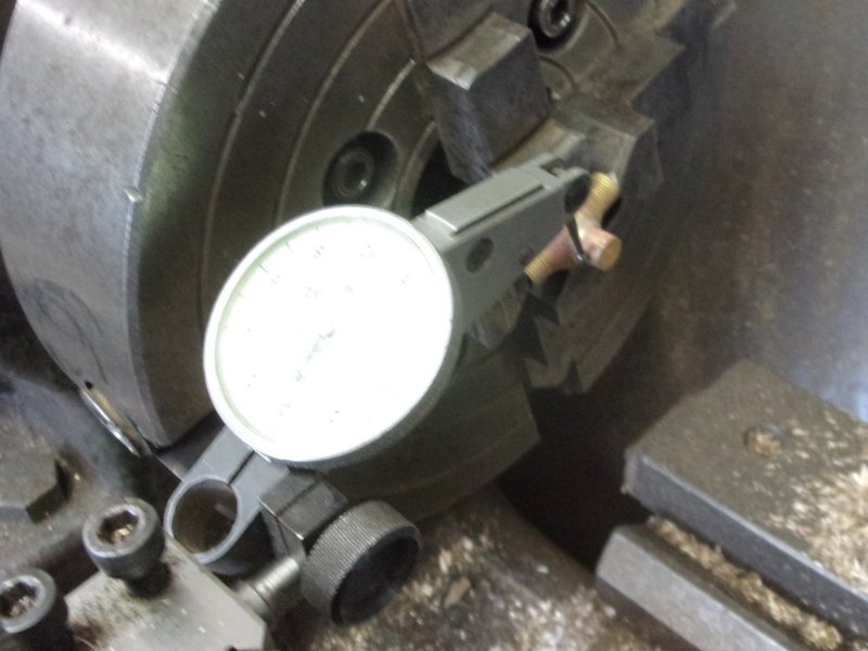
Once the globe valves were removed from the pickle and
washed, the next job was to machine the spindle branch. To ensure this was
running true, I used the drill chuck to align and load them to the independant
4-jaw chuck. It might have been smarter to use 5/16" diameter material and
skim it down but it's what it is. With the branch axially aligned to the
lathe centreline, they were then clocked for minimal runout. |
 |
 |
It was important to be able to control the depth of the
drill and not penetrate through the base of the valve so I set up my spare
digital caliper in the contraption I cobbled up a few years ago. I made
sure that the 3/32" pilot drill didn't exceed 5/8" deep, leaving about 1/16"
wall thickness at the bottom. This was followed with a 3.3mm drill that
I resharpened as a counterbore, then tapped 5/32" x 40 tpi although I could
have used M4 if I had thought about it in time. The 1/4" x 40 tpi outside
thread was cut last. Setting the parts to drill the angled steam ports was
achieved by holding them, tilted over, in a small machine vice using the
counterbore drill to help set it true in the other plane. Not easy to describe,
nor to photograph, unfortunately. |
 |
 |
This vice was then held in the main milling vice and the
hole drilled using a PCB drill. Alignment was done purely by eye; as long
as the drill meets the drilled spindle hole then all is well. The opposite
end was done by turning the vice over. The draughtsman doesn't show a spindle,
he had obviously lost interest by this time. Design your own seems to be
the order of the day and I have made mine from 5/32" diameter stainless
steel. I have designed my spindle to act onto a 1/8" diameter ball bearing
and to be captive in the valve. Length is also an unknown until the pipework
is in place and my best guess is about 3.1/4" max. The front of the spindle
was reduced to 0.115" diameter by 3/16" long, then threaded 5/32" x 40 tpi.
|
 |
 |
The main part of the spindle was reduced to 1/8" diameter
by holding on the front turned portion and supporting the far end in a hollow
live centre. The middle section grew a few thou, as expected, and was abraded
out with emery cloth. I left about 3/32" length of thread.The final picture
shows the component parts of one valve and the other assembled. Once the
final overall length is known, a square will be milled on the end for a
handwheel. I also need to make a pair of gland nuts to hold the spindle
captive, the one shown is a standard pipe nut with oversize hole. This type
of valve is directional, steam flowing right-to-left as drawn, and I have
embossed arrows on the valves to ensure correct orientation. |
 |
| 6. Blower Stop Valve |
|
|
 |
Finding another excuse for not sorting the top profile
of the boiler, I made up a nice little valve for the blower. This is a kit
of four body castings plus other materials to complete the valves. I made
one change because they supplied brass rod to make the valve stem and I
substituted stainless steel. I found it easier to machine the whole of the
spindle complete before parting off. The rest of the parts were straightforward
turning although depths had to be controlled quite precisely. The wall thickness
between the valve bed and the inlet port is only thirty thou or so. I have
substituted ME threads for the American National Fine threads specified
on the drawing and I also made a square end on the spindle for a positive
drive for the handwheel. |
 |
 |
Steam is taken from the manifold and passed through the
dummy duplex valve before passing through my valve and on through the hollow
blower stay. Here it is mounted on the cleading. When Wilf and I were building
the boiler, Adam Cro mentioned how unsightly and un-prototypical the pipework
to the blower stay looked, spoiling the clean lines of the backhead. The
suggestion was to run the pipe outside, as in fullsize. This is my compromise
that uses the hollow stay but, effectively, hides the pipework from sight
below the regulator with it passing behind the false backhead. |
 |
| Blower Update 31/01/2021 |
|
|
 |
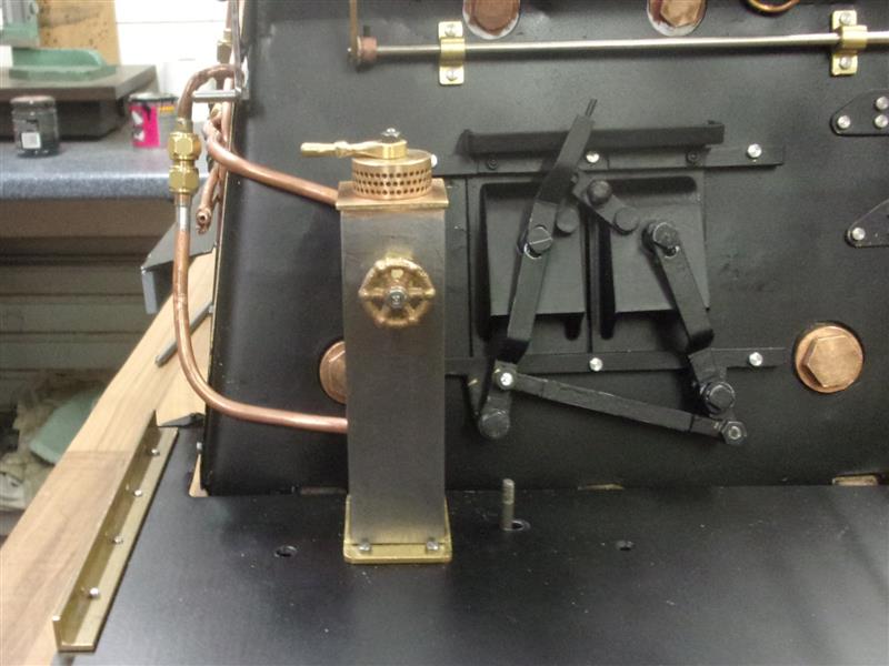
I've had to completely re-think the blower valve after
finding that my original idea fell foul of the reverser box. The idea was
to keep the backhead looking as close to prototype as possible and the as-drawn
solution placed a valve below the left-hand gauges. I've also decided to
dispense with the steam brakes so have stripped all the bits from within
the driver's pedestal. The blower will go here instead in it's rightful
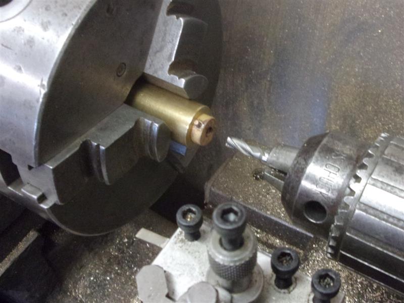
place. First job was to mill away the material at the back of the column.
Next, the column was turned over and a 1/4" dia hole drilled and reamed
near the top of the front face. The valve I made was then mounted within
the column, using the valve spindle collar to hold it in place. The next
picture is taken looking upwards from the base. |
 |
 |
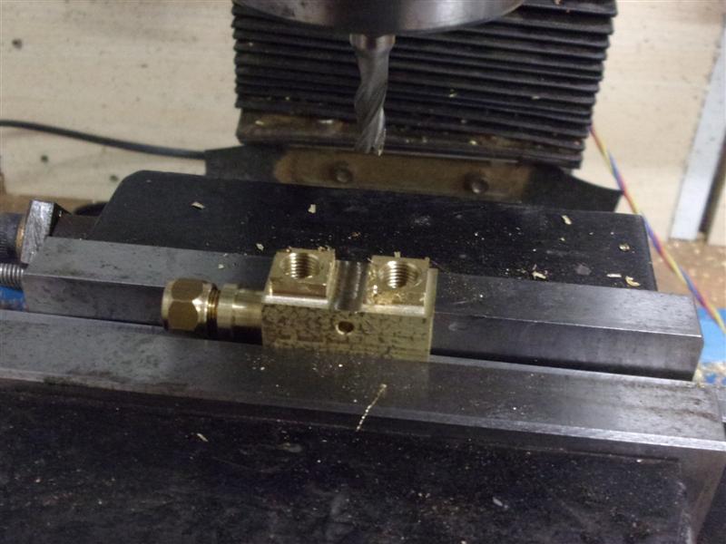
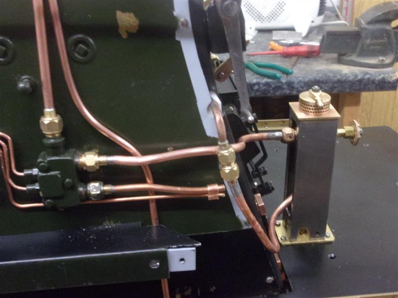
New pipework was made to connect the dummy duplex valve
to the pedestal, and the outlet of the valve to the boiler blower tube using
a nipple to effect the join. This ensures that the pipework can be dismantled
without wrecking the cab if it becomes neccessary. This is the front view
of the pedestal, the brake vent on top being purely decorative. This is
the pipework from the side showing entry to the pedestal and exit to the
blower tube. Most of this is in the cab and out of sight, but shows how
easy it is to dismantle in the future. It is also well clear of the reverser
rod. Once painted, the pipework will be all but invisible. |
 |
| 7. Dummy Injector |
|
|
 |
The dummy injector is made from various pieces
of brass bar with all the branch sections screwed into place and soft-soldered.
I am using the dummy injector as a means of routing the handpumped water
to the front nearside clack. The lower branch section was made from 3/4"
dia brass, turning the front end and a section behind the flange whilst
the "bend" was formed by grinding and filing away the surplus.
Under a coat of black paint, it won't look quite so rough. That and the
top feed-out were threaded 1/4" x 40 to attach them to the main body. |
| 8. Carriage Warming Valve |
|
|
 |
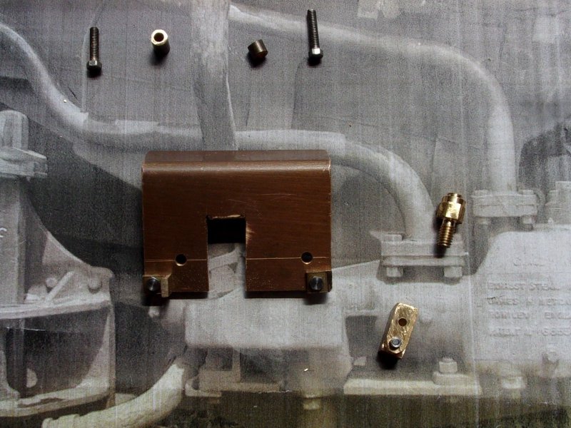
The carriage-warming valve, which is mounted
high on the fireman's side of the firebox, is a particularly complex valve
and difficult to fabricate in miniature so I have bought one of Adam Cro's
excellent castings. Although the valve is a dummy, the detail is exquisite;
much better than the simplistic one on the drawing. They are not that easy
to hold so the first job was to freehand drill the three mounting holes.
12BA would be the recommended bolts for holding this but my 10BA and 12BA
bolts both have the same size head, the modern 2.5mm A/F, so I've gone with
the more robust 10BA.. |
 |
Then I squared up a piece of 3/8" thick mild
steel plate and drilled and tapped mounting holes for the valve. In this
picture, the valve is not in the correct orientation but it matters not
and the dimensions reflect this. After bolting to the plate, the various
holes for the pipes were drilled by moving the fixture around in the vice.
All the holes are on the same centreline so it was just neccessary to line
up the "X" position. The first one was for 1/16" dia copper pipe. |
 |
 |
When drilling the 3/16" hole for the outlet pipe, extra
support was added beneath the casting with packing and a feeler gauge. The
material is silicon-bronze which is quite tough and somewhat abrasive so
drilling needs to be done more slowly than expected and with cutting fluid.
The other holes drilled were 1.2mm for the pipe to the gauge in the cab,
1/8" for the supply pipe and 3/32" for the valve spindle. Finally, the casting
sprue at the outlet elbow was linished off and the valve mounted on the
firebox cleading. Now I can get on and paint everything and, once all the
pipes are fitted into place, the valve will then really look the part. |
 |
| 9. Hose Connectors |
|
|
 |
The hose connectors have been made from 1/2" dia
brass and turned or bored to suit 3/8" x 32tpi. Next, they were cross-drilled
3/32" and a 3/4" length of 3/32" dia brass silver-soldered
in. Then they were returned to the lathe and the centre section removed
with a slot drill, boring and retapping the female parts. The male components
were bored 1/4" dia x 1/8" deep on the back for silver-soldering
to 1/4" dia copper pipe. |
 |
 |
The hose nipples were made from 5/16" dia brass,
turned to 7/32" dia x 1/2" long and a 1/4" long undercut
made with the parting tool, about 20 thou deep. A 5/32" dia hole was
drilled through and the front shaped with a 45 degree tool before parting
off. The hoses I am using are bicycle pump flexible tubes and 7mm double-ear
clips are used to secure the pipe to the nipple because they are much smaller
and neater than other forms of hose clip. |
 |
| 10. Next Item... |
|
|
| |
|
|