| Drawing 5 - Bogie
|
| 1. Bogie Frames |
|
|
 |
I made the front bogie assembly many years ago but there
are still some bits needed to finish it. The two side frames were marked
out and then cut to shape, using hand tools only, before co-ordinate drilling
all the holes using the Bridgport with its DRO. There were also quite a
few components that had to be made and rivetted to each side prior to rivetting
the two end stretchers including the horns, the guard irons, the lower spring
supports and the pressure brackets. |
 |
 |
The inner horn blocks needed to be cut away to clear the
equaliser bars but I didn't remove enough metal before assembly, hence the
saw marks on the sides. One of those situations where I wish I had used
rivet-headed screws instead or rivets, they could have been dismantled and
worked on further. The main centre bogie stretchers, which are also the
guides for the sliding block, were also made at this time but I had chosen
to fix these using screws instead of rivets. |
 |
| 2. Kingpin |
|
|
 |
The kingpin was made from some 7/8" diameter
mild steel just held in the 3-jaw chuck and the pivot end turned down to
1/2" dia by 1.3/4" long followed by reducing the front to 1/4" dia and threading
1/4" BSF. I didn't form the two tapers at this point as I wanted to chuck
on this diameter to turn and thread the opposite end. After the second end
was done, I reversed the work once more, holding on the short length of
3/8" dia and machined a slight taper from the front to the half-way mark
using ther compound slide set at about two degrees. Then I set it over the
other way and ran from the middle to the shoulder, finishing off with some
emery cloth to blend it all in. I wasn't bothered about concentricity for
this, nor are the sizes overly critical - a couple of thou under nominal
seemed about right. The dull black finish is the phosphate finish that I
had applied at the time. |
| 3. Sliding Block |
|
|
| Next I had to make the sliding block which
fits between the centre stretchers and drops over the kingpin. There is
a gunmetal casting available for this but I had a lump of bronze available
so used this instead. This was made many years ago but my notes remind me
that I first faced up the billet in the lathe and drilled the hole 7/16"
diameter. Then I turned the billet round, faced the opposite end to length
(1.1/8") and then bored and reamed the 1/2" hole to size. I then loaded
the block to a 1/2" diameter mandrel held in a 4th axis chuck on the table
of the bridgeport and machined all the sides, finishing off by putting the
spring retaining reccesses in with a 3/8" dia slot drill. The photo does
show one difference from the drawing, the four tapped holes in the bottom
of the block that I will explain once the bogie is fully assembled. |
 |
| 4. Axle Boxes and Axles |
|
|
 |
I have made the axleboxes in the same matter
as for the pony truck (page 6) so wont cover the same ground again and,
likewise, the axlebox covers. As before, I have dispensed with the oiling
holes as I am using sealed-for-life bearings. If they fail in service, it's
no big deal to press the wheels off and replace the bearings. The axles
were turned from some 5/8" dia EN8DM. I roughed them out first just holding
in the 3-jaw chuck and leaving about fifteen thou on the diameters but getting
the 3.543" length bang on size. The bearing journal length of 0.572" is
not actually that important as long as it is not over length. This is because
the wheels are pressed on with spacer collars between the bearing and the
wheel to set the back-to-back distance between wheels. . |
|
 |
Second op was to hold on the bearing journal using some
brass shim to protect the surface and turning the opposite end diameters
using a rotating centre to keep things running true. The bearing diameter
was machined as a light press fit and the wheel journal with a half- to
one thou interference fit which will be tweaked later if needed, depends
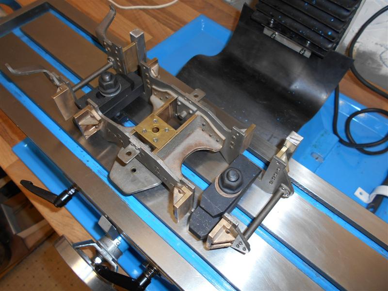
on how the reamer cuts. Once machined, I assembled both axles into their
respective axleboxes and then checked the width across the bogie horns.
This turned out to be a bit oversize so I then mounted the bogie to the
table of the new mill, pushing the rear horns up to a pair of tee-slot packers
and clamping as shown. |
 |
 |
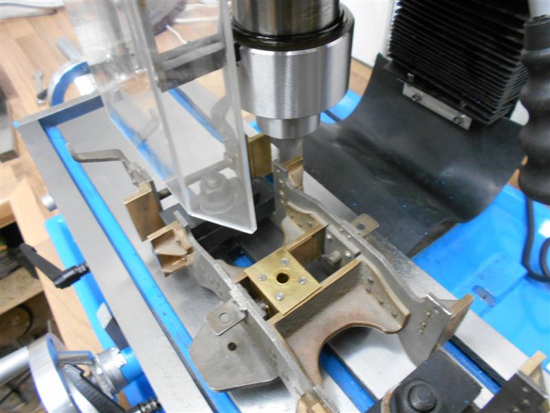
Then the tee-slot packers were removed and the horns to
the rear given a light skim with a long-series endmill. I then came round
to the front horns and dressed those to the correct dimension. Final job
for the moment was to start polishing the horn block faces for a nice sliding
fit of each assembly although I will probably need to ease these down to
a light rattle fit later on but they will do for now. Apart from making
the spacer collars and pressing on the wheels, all I need to do now is fit
the axle keeps below the horn blocks. |
 |
| 5. Equaliser Bar |
|
|
| The bogie suspension comprises a single leaf
spring each side with an equaliser bar rather than independant suspension
to the four wheels. At this stage, I am following the drawing and using
the dummy spring castings with the hidden coil springs but I will replace
them later with properly-constructed springs even though they are almost
entirely hidden within the equaliser bar. The supplied castings are aluminium
and I think that there will be a weak spot at the point where the spring
support bars screw in and they may well break in service. They're junk but
will do for now while I get further along the build. The centre section
was just cleaned up in the mill to get some square faces to work with and
then the holes drilled. The spring support bars were made at the same time,
just threading some 3/16" diameter mild steel with 2BA |
 |
 |
I marked out the four equaliser bar side
plates on some 16 swg mild steel and then cut out the shapes with hacksaw,
stitch drilling and carbide burrs although I deliberately made them longer
to accomodate the bends at each end. Then I made the four spacer blocks
from some 1/2" square mild steel which I drilled and then parted off in
the lathe. Also made, from some 5/16" square mild steel, were the four spherical
pressure pads. The radius was formed with a form tool and each one then
parted off. I drilled all the holes in the side plates and the spacer blocks
to take the rivets and then changed my mind, deciding instead to use 8BA
countersunk screws rather than rivets, so all the holes were modified to
suit, deep countersinks being formed in the side plates and 8BA tapped holes
in the blocks. |
The next job was to bend the offsets into
the ends of the side plates and, since the step-over is only 3/32", this
was done freehand in the bench vice. They were adjusted until, when assembled,
they gripped the 5/16" square shanks of the pressure pads which were then
positioned over the centre-line of the axlebox and clamped in place. Then
the cross-hole for the rivet was drilled and the pressure pads riveted into
place. Getting everything placed correctly was the most fiddly and difficult
part of this job. Finally, the spring support bars were screwed into the
dummy springs, assembled into the equaliser bar and the coil springs with
their retaining nuts fitted. |
 |
| 6. Eccentric Strap |
|
|
 |
To make the strap, I cut some blanks from a section of
5/16" brass plate. To get the size, I placed some tracing paper over the
drawing and roughly sketched round the form and then fixed this to the plate
with spray-mount adhesive. The two pieces were then roughly cut out and
the two mating faces linished flat followed by milling the clamping faces
at each end of the two halves. I also formed the rest of the outside shape
with the linisher, files and my dremel.Next I marked out the screw holes
and drilled them 1/8" to be a good clearance for the 6BA bolts and also
milled the slot to take the coupling arm and drilled the three rivet holes. |
 |
 |
The two halves were then nut and bolted together and
put into the four-jaw independant chuck on the lathe and the 1.11/16" diameter
bore machined out to size. I found that a very light touch was neccessary
when tightening the jaws as I could see the whole thing deforming. After
getting to within ten thou of finish size, I loosened the grip right off
and gingerly took a couple of final tiny cuts. This is not the best way
of doing this job! Clamped to a faceplate might have been the smarter option.
The last two jobs were to rivet the arm to the strap and drill the oil hole
prior to giving the parts a polish to get them running smoothly. |
 |
| 7. Eccentric Oiler |
|
|
| The drawing doesn't offer any means of accessing
the oiling point on the eccentric strap and it appears to be nigh-on impossible
to get in there once the boiler is in place. I have chosen to mount an oiling
dashpot on the upper stretcher with some flexible tube connected to the
eccentric via a short piece of 1/8" dia copper tube. Whether the plastic
tube will last for any length of time remains to be seen but it's better
than trying to get an oilcan spout into the restricted space. Positioning
it behind the weighshaft but ahead of the driving wheels leaves enough space
to flip the lid and fill the pot. It can also be seen that I have modified
the stretcher by removing the central section and mounting the two remaining
sections separately. |
 |
| 8. Front Vacuum Pipe |
|
|
 |
I've used a piece of 7/32" dia solid copper rod to make
the front vacuum pipe, salvaged from an old consumer unit. It's easier to
bend without distorting than brass, and copper tube would collapse with
the sharpness of the bends. It took three annealings to get it to the right
shape then it was pickled before soldering the adornments on. The three
rings were made from copper wire wrapped round a former, the lower clip
from some 24swg brass and the pipe clamp from 1/2" x 3/16" flat brass bar.
This has to be recessed deep enough to let the pipe stand off 1/8" from
the buffer beam. The top of the pipe was drilled and tapped 10BA to take
a short length of studding and the flexible pipe (curtain wire) is just
pushed over it. |
 |
| 9. Next Item... |
|
|
| |
|
|