| Drawing 3 - Main Axles and Wheels
|
| 1. Main Axles |
|
|
 |
The axles are just a bit of simple turning. I have made
mine from some 3/4" diameter EN8DM material that we always had in stock.
40-ton tensile so tough but nice to machine because of the slightly higher
level of Manganese in it. First, I just roughed them out using the 3-jaw
chuck and a back-stop, leaving about fifteen thou to come off the two journals
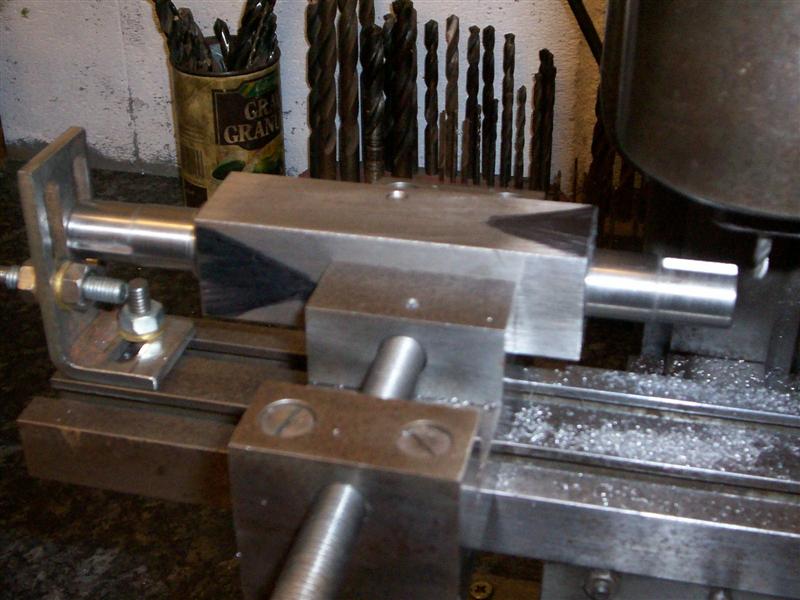
but finishing them to length at this visit. After that, I set them up as
shown to finish the diameters. A purist would probably use centres at both
ends and a driving dog but my chuck runs true enough to grip one end and
run the other in a live centre. |
 |
 |
Having a shoulder for the chuck jaws to push
on also helps when it comes to winding up the centre otherwise the work
would probably creep backwards as the cut came on. I also changed over to
a bit of HSS tooling here, partly because my rhomboid tool wouldn't fit
anyway. It's also easier to take tiny cuts with HSS and we are talking a
few tenths tolerance here. The pictures make the finish look rubbish but
it's a trick of the light, they are actually very smooth. The last job that
I needed to do on the axles was to mill the quartering keyways in the axles.
This is not as per drawing but I have read many pages of discussion on the
merits of either keys or Loctite to prevent the wheels from moving on the
axle and decided that I prefer to use keys. It requires no fancy quartering
jig to get them right first time, and they definitely will not move once
pressed on. The easy way would be to mount the axles in a rotary table or
dividing head on a milling machine. |
 |
However, I have neither but I did have a lump of 1" square bright mild
steel bar and a length of this was used to make an indexing fixture, faced
off in the lathe and a 3/4" hole drilled through it. I also added an M5
clamping grub screw about half-way along. Britannia has a right-hand lead
so the fixture was marked accordingly and each axle loaded in turn to
the fixture which was then held in the milling vice and the first keyway
cut with a 1/8" slot drill. The fixture was then removed from the vice,
up and over-ed and set back into the vice for the second keyway.
|
 |
| 2. Axle Boxes |
|
|
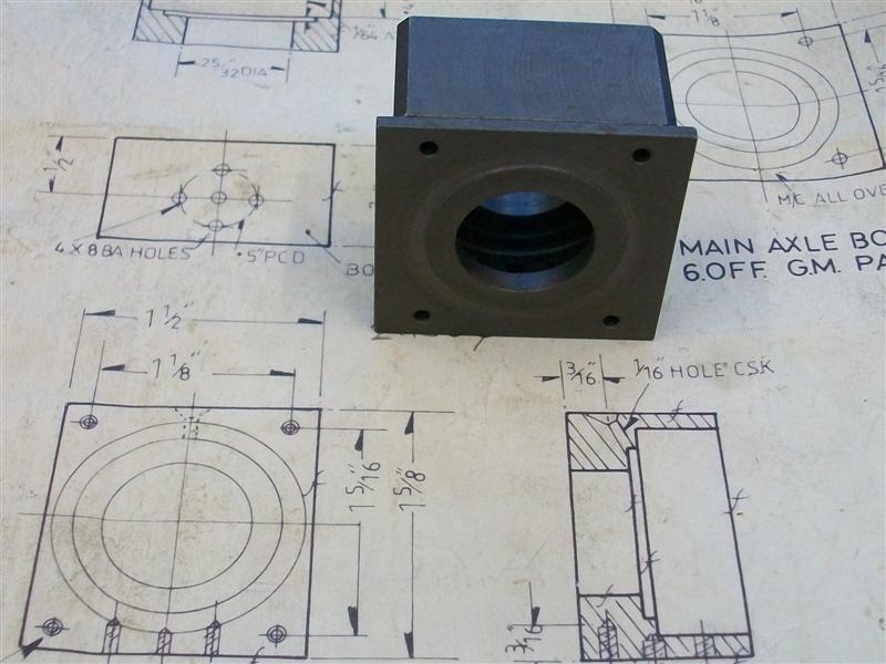
| The drawing suggests using the available gunmetal castings to make to
main axle boxes but I have made mine from round mild steel billets. I would
have used 2.1/4" dia material but I only had 2.1/8" at the time and that's
why the corners are chamfered. The back face was first cleaned up on the
lathe using the 3-jaw chuck and the billet was then reversed and all other
turning ops completed in one go. Depths are quite important here because
the distance from axle box face to bearing depth to axle shoulder, across
the axle and back up the other side to the other axle box face has to fit
the distance across the horns. Bearing diameter is, obviously, also important.
Because of this, after drilling the through hole I chose to do all the bores
and faces at one visit using a single boring bar and using the compound
slide for varying the depths. I aimed for a light press fit on the bearing
bore. Once all six were done, I marked out the finish position, plus about
thirty thou, of one of the sides and then hacksawed the waste off and linished
them reasonably flat. This made it easier to mark out the other three sides
and rough those out as well. I chose to remove most of the waste with a
hacksaw to save knocking the guts out of my tiny milling machine. To finsh
machining the four sides, I just loaded them to the milling vice and flycut
the top and bottom edges first, keeping a check on the wall thickness to
make sure the bearing bore stayed central. Then the sides were done in a
similar fashion although a little more care was taken here to get the size
bang on. All that was left to do was to mark out all the various holes and
then drill and tap as appropriate. I wont bother with the oil holes, though,
because I am using sealed-for-life bearings. |
 |
| 3. Axle Box Covers |
|
|
 |
The main job of the axle box covers is to control side-to-side movement
of the axle where the outer edges bear against the gunmetal horns, although
they are handy for holding the bearing firmly in the axle box. I have made
the covers from billets sawn from 2.3/8" dia mild steel bar although gunmetal
casting are available. I don't see the point since the horns are made of
gunmetal and similar metals often fret if rubbed together. After deburring
the edges and mounting them to soft jaws I first faced them off to clean
up, followed by drilling and boring the 25/32" diameter axle clearance hole
and clearing the bearing relief area still using the boring bar. I did all
six like this before reversing them in a separate operation and facing the
back, or outside as it will become, and forming the 1.1/8" diameter x 1/64"
deep relief on that side. Finally, they all went back into the soft jaws
for a third operation which was to turn the main axle box locating spigot
which I made a thou or so smaller than the bearing diameter. |
 |
 |
After that, they were sawn and milled an edge at a time to arrive at
finished size, just holding vertically in a vice or, in my case, bolted
to a faceplate and rotating round using a square to set the position. Accuracy
is not important here, it's the axlebox with it's bearing depth that controls
everything. Once they were all milled to size the only things left to do
were to mark out and drill the bolt holes and then pair each one up with
an axlebox, spot through and finally drill and tap the axleboxes. These
are now ready for assembling with the bearings and axles although I will
have to remember to make the pump eccentric for the centre axle first and
slide it on before pressing the bearings on. |
 |
| 4. Driving and Coupled Wheels |
|
 |
The driving and coupled wheels have the balance weights cast in and, consequently,
are quite heavy but also out of balance at this stage. This meant that the
lathe rocked quite a bit at higher rotational speeds. Since most of the
turning was done at low speed, I decided that it wouldn't be worth trying
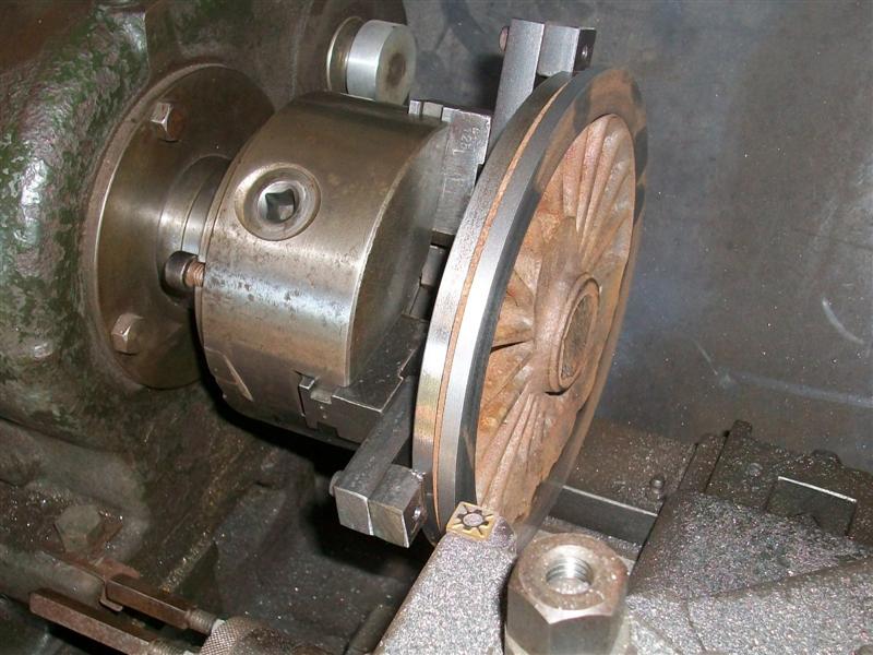
to balance them with some bolt-on weights. First operation was to hold the
flange diameter in the four-jaw independant chuck and try and get the best
visual balance for the spokes and rim. The front was then faced and the
tyre diameter turned about fifty thou oversize and a decent chamfer filed
on the outer edge. |
 |
 |
All subsequent operations were done in the three-jaw self-centreing chuck
using home-made soft jaws because the chuck is a 5" diameter and the wheels
are 6.9/16" at the major diameter. This method was chosen because it's quicker
to load and get machining each op - soft jaws give good repeatability -
and I don't have a large faceplate and didnt fancy spending all year clocking
the wheels up at each operation. The jaw extensions are just bolted on with
M5 cap screws but they will be perfectly OK for this application. |
 |
 |
Once the jaws had been bored to suit the back was faced as a single operation,
then the flange diameter turned and the axle hole drilled and bored to about
fifty thou shy of finished size, all as separate operations. A ten thou
depth of cut was used for all of the facing operations and each pass took
about five minutes. Luckily, I have automatic feed in both axes so was able
to use the waiting time to fettle out the flashing between the spokes with
files and rotary burrs. I didn't count the number of separate operations
but it must have been a dozen or so. When there were only two operations
remaining, I reskimmend the jaws and also reduced the depth to seventy thou
to give me room to form the angle on the flange with a form tool. |
 |
 |
The last but one operation was to finish the axle hole and to size but
I don't have a 9/16" reamer so I had to use a boring bar to get to final
size and that brings it's own problem - measuring the bore! I used a spare
axle and polished one of the journals down a thou to give me a Go/NoGo gauge.
Once all the bores were done, I set the compound slide to two degrees and
formed the two degree angle on the tyre diameter. However, just to be on
the safe side, I clocked the bore and checked that the runout wasn't excessive
before machining each wheel. It never went worse than half a thou. |
 |
 |
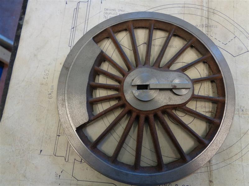
To finish the driving and coupled wheels, they needed
the holes for the crank pins made, the pins inserted and the keyways cut
into the bore. The latter is not to drawing but is how i've chosen to quarter
(and retain the setting of) the wheelsets. The position of the crank pins
needs to be very accurate across all six wheels and I have, therefore, chosen
to use a drill jig for this purpose. The jig is just a piece of 1.1/4" x
1/4" flat bar drilled and reamed 1/4" dia to take the locating peg at one
end, drilled and reamed 1/8" dia at the crank-throw position and drilled
and reamed to take another pin to locate between the spokes. |
 |
 |
Using the jig, the crankpin holes were first drilled 1/8",
then opened up to 23/64" with a drill that I had modified for cast iron,
and finally reamed 3/8". The next job was to make the keyway bush with an
alignment slot and a bush with a similar alignment slot to fit the crankpin
holes. The two bushes were turned from some suitable mild steel and a 3/16"
alignment slot milled into both. These need to be a good fit to the alignment
bar to ensure that the keyway position is consistent across all six wheels.
The keyways were cut using three passes of my home-made keyway broach (covered
in a separate article HERE) just using my simple,
lightweight drill press. |
 |
| 5. Crank Pins and Endcaps (see
the Assembly page for further work) |
|
| The crank pins and end caps were made from various offcuts
of mild steel and are straightforward machining operations in the lathe.
The most important part is getting the diameters accurate and concentric
so the 3/8" diameters for press-fitting into the wheels and the bearing
diameters were turned in a single operation prior to parting off. Each of
the pins was then held in the 3-jaw self-centering chuck for any subsequent
operations. There are two pairs and two individual pins that go to make
up the set although they all have a common locating dia. The nearside rear
crankpin differs from the offside because the speedometer bracket bolts
to it. |
 |
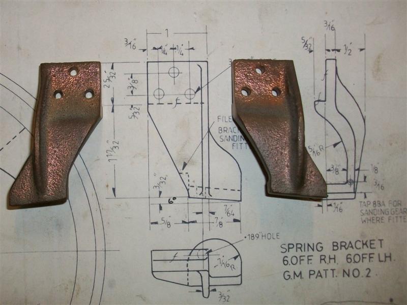
| 6. Spring Brackets |
|
|
 |
Because the spring brackets are difficult to hold I decided
to make a mould to rest them in for the first milling operation. Some air-drying
modelling clay was first placed in a matchbox then the casting, wrapped
tightly in clingfilm, was pressed into it and levelled by eye. There are
left-hand and right-hand parts so I then had to repeat the process for the
opposite hand. These were then left to dry for a couple of days on the workshop
windowsill. Once the moulds had gone nice and hard it was time to do a bit
of machining. |
 |
 |
First, each spring bracket was loaded into the respective
mould with a tiny bit of foam underneath and then the whole lot was clamped
gently onto the mill table, again lining up by eye. By taking small cuts
I was able to mill the frame mounting face and register, the top edge and
part of the side edges.This would be enough to enable subsequent operations
to be done much more easily. Because I was able to machine the side edges,
I could now hold the workpiece in a vice and machine the other side. |
 |
 |
The reason for doing this, since they bolt to the inside
of the mainframes, is to make it easier to mark out and drill the holes
and to provide a good seat for the bolt heads or nuts. This is an example
of where a set of soft vice jaws comes in handy. To machine the lower faces
of the spring brackets I first drilled and tapped a bit of flat bar to match
the bracket holes and then set this at 6 deg. on a small angle plate. I'm
using a couple of angle gauge blocks but there are lots of other ways of
setting the angle. |
 |
 |
It was now a simple matter to just bolt the spring brackets on and flycut
the face, reversing the fixture at the half-way stage for the other hand.
The holes were spotted with a centre drill while the fixture was set on
the mill and then the whole lot moved to the drilling machine and the holes
drilled freehand. Finally, some of them need a little bit of extra work
to allow mounting of the sanding gear and this was done using the same fixture
just bolted vertical on the faceplate. These will be bolted on a bit later, |
 |
| 7. Spring Hangers |
|
|
 |
I've had to make the main spring hangers different to
drawing because I messed up on the axle boxes - I marked out the fixing
holes from the wrong face and, consequently, the hanger pin would be out
of position. I had no intention of scrapping the axle boxes after that amount
of work so modified the spring hangers to suit. Rather than a circular base
as per drawing I've made this part from a rectangle of 10swg mild steel
plate and marked out the holes to suit. The rod part is 3/16" dia mild steel
with a 2BA thread on each end but without the titty as there is no location
point for it on the axle box. I will silver solder the two parts together
a bit later on, I just need to find a way to hold the whole thing square
while soldering. |
 |
| 8. Main Springs |
|
|
 |
I have made the main springs from the castings
and, although gunmetal ones are available, I was sent aluminium ones twenty-odd
years ago. They are extremely poor quality and I will probably make proper
leaf springs at some point in the future. I milled all round the buckle
to clean the casting up and then milled the back of them. The spring holes
were straightforward but the castings were set (by eye) in the vice at five
degees to drill and tap the spring anchor points. |
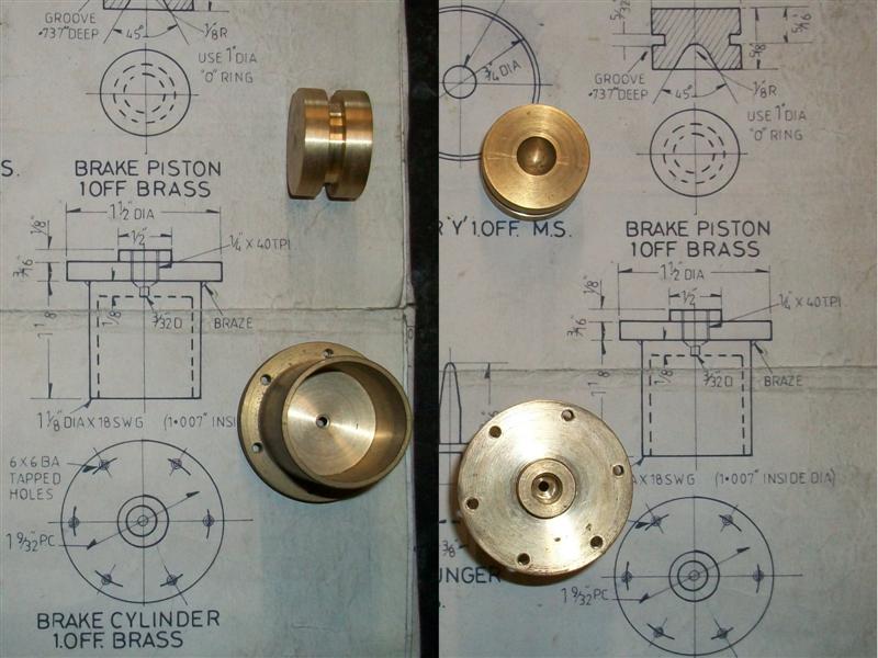
| 9. Brake Cylinder |
|
|
| The drawing indicates that the steam brake
cylinder is made from a bit of brass tube brazed onto a machined boss but
i've made mine from solid using 1.1/2" diameter brass. Because of this,
it won't matter what size I make the bore (within reason) as long as I machine
the "O" ring groove to suit. I decided to turn the back end first, facing
and turning the 1/2" spigot, drilling and tapping the steam entry port and
skimming the O/D. I then loaded it to soft jaws to machine the opposite
end. I went this way because the wall thickness of the cylinder is a bit
thin and I didn't want to risk distorting it with any form of chuck pressure.
First, the billet was faced to length, then drilled and bored to my chosen
size of 0.994" and finally the O/D was turned to size. Then it was removed
from the chuck, offered up to the brake cylinder bracket and the six bolt
holes spotted through. These were then drilled on the drill press and tapped
6BA by hand. |
 |
 |
The piston was made from 1" diameter brass skimmed to
be a sliding fit in the bore of the cylinder with an "O" ring groove cut
into the O/D to provide the seal, finishing this diameter at 0.724". The
locating hole for the operating pin was made by drilling with a No.4 centre
drill and plunging with a small high speed steel form tool made to suit
which I have since lost, so can't show it here unfortunately. Finally, it
was deburred and parted off |
| The few remaining items to complete the brake cylinder assembly
were the pivot pin, the bell crank, operating pin, a couple of clevis pins
and the return rod with spring. With regards to this set of drawings, anything
which is specified as 1/8" dia with a 5BA thread is replaced by 3mm material
with an M3 thread. The pivot pin is just a piece of unhardened 5/16" diameter silver steel,
The operating pin was machined from a bit of 3/8" square mild steel, holding
in my self-centring 4-jaw chuck to turn the 1/4" diameter and just filing
the shape on the end. The fork was made the same way as I make all my forks,
held vertically on the mill and machined through with the appropriate slot
drill. The bell crank was made as two pieces and brazed together. |
 |
 |
This is
a picture of the whole assembly and here it is mounted between the frames.
I have drilled and tapped a cross-hole in the bell crank to take an M3 cap
screw and by locking the bell crank to the shaft I don't need to silver
solder the bushes into the framework, just a dab of Loctite, so if they
wear out (unlikely) I can just make a new pair and drop them in. |
 |
| 10. Screw Couplings |
|
|
 |
The first thing I did was to turn up a simple former with
a 5/16" diameter core size and bend four pieces of 1/8" dia stainless steel
tube around it. I've found that this material takes tight bends without
distortion if it is in a bending former. Using tube allows me to use 1/16"
diameter pins to locate the eyes onto. The various components for the screw
were made from 5/16" square mild steel, 1/4" square MS and other mild steel
rounds as appropriate. There is quite a collection of parts to make two
couplings. The only deviation I made from the drawing was to make the screw
parts M4 rather than 5/32" x 40. Also, the lock collars are an interference
fit allowing me to dispense with cross pins. |
 |
 |
The eyes were made from 3/8" diameter mild steel and radii
just filed on the outer edges prior to parting off. A 1.6mm dia hole was
drilled through from the outside diameter to the centre hole, this being
an interference with the 1/16" pins fitted in the ends of the coupling,
and the assemblies pressed together in the vice. The whole assembly is press-fitted,
no soldering, as it is a cosmetic item only. The last photo shows one mounted
on the front draw-hook along with the vacuum pipe and the carriage heating
pipe. |
 |
| 11. Next Item.. |
|
|
| |
|
|